Solutions · New Technologies & Innovation
Advanced EDI with Low Energy Consumption: 18.2 MΩ·cm quality with ~20% less stack power
Current efficiency, resin stratification, and segment voltage: third-generation stack design for fabs and injectable loops.
Use this guide within its scope
This page supports technical research and option comparison and is marked 2026. Illustrative values are not a quotation, completed process design, certification conclusion, or performance guarantee. Check current regulations, feed data, tests, and OEM records.
Problem
UPW loops are kWh-intensive; buyers want Ω·cm stability without heroic stack current.
Technology
Optimized cell pair count, thin chambers, and brine/concentrate management that cuts I²R waste.
Results
Defensible kWh/m³ deltas versus legacy stacks in comparable inlet-quality cases.
Engineering decision card
Use when
UPW loops are kWh-intensive; buyers want Ω·cm stability without heroic stack current.
Evaluate first
Optimized cell pair count, thin chambers, and brine/concentrate management that cuts I²R waste.
Inputs still required
Feed source and variability, capacity, target quality, operating hours, discharge or reuse boundary, available space, and utilities.
Comparison output
Defensible kWh/m³ deltas versus legacy stacks in comparable inlet-quality cases. The final decision still needs feed data, mass balance, and any necessary testing.
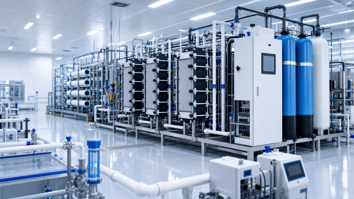
Understanding the Physics of Energy Consumption in EDI
Electrodionization combines ion exchange resins and ion-selective membranes under an electric field to continuously deionize water without chemical regeneration. The primary energy consumer in an EDI stack is the electrical power required to drive ions across the membranes and through the ion exchange resin beds. This power is largely dissipated as heat due to the ohmic resistance of the system.
The electrical power () consumed by an EDI stack is fundamentally governed by Ohm's Law and can be expressed as:
where is the applied current, is the total electrical resistance of the stack, is the applied voltage, and is the Nernst potential (thermodynamic minimum voltage required for ion transport). The stack resistance is a complex function of the water conductivity, membrane resistivity, ion exchange resin resistivity, and stack geometry. It can be further elaborated as , where is the specific resistivity of each component (dilute compartment, concentrate compartment, membranes), is its effective thickness, and is the effective cross-sectional area for current flow.
- Optimized flow path and compartment design: Minimizing the electrical path length and maximizing the effective area for current flow, especially in the dilute compartment where resistivity is highest.
- Advanced ion-exchange resin matrices: Utilizing resins with enhanced ionic conductivity and uniform packing characteristics, which reduces local "hot spots" of high resistance.
- Improved membrane materials: Deploying ion-exchange membranes with lower intrinsic electrical resistance and improved selectivity, reducing the energy needed to drive ions across.
- Intelligent control algorithms: Dynamically adjusting voltage and current based on feed water quality and desired permeate resistivity, ensuring operation at the optimal point between efficiency and performance, often just below the limiting current density to prevent water splitting and scale formation.
By addressing these fundamental physical and chemical parameters, this approach's advanced EDI technology achieves a significant reduction in the specific power required per cubic meter of 18.2 MΩ·cm UPW produced.
Illustrative pilot / lab comparison
| Parameter | Traditional process | engineering evaluation path innovative |
|---|---|---|
| Specific Power Consumption (EDI stack) | 0.25 kWh/m³ | 0.20 kWh/m³ |
| Operating Current Density | 5.5 A/m² | 4.8 A/m² |
| Outlet Resistivity (typical) | 18.0 MΩ·cm | 18.2 MΩ·cm |
| Water Recovery (EDI stage) | 90% | 92% |
| CIP Interval | 6 months | 9 months |
Illustrative numbers only. Actual performance varies based on feed water quality, temperature, and specific operating conditions. Performance guarantee requires site-specific engineering and pilot data.
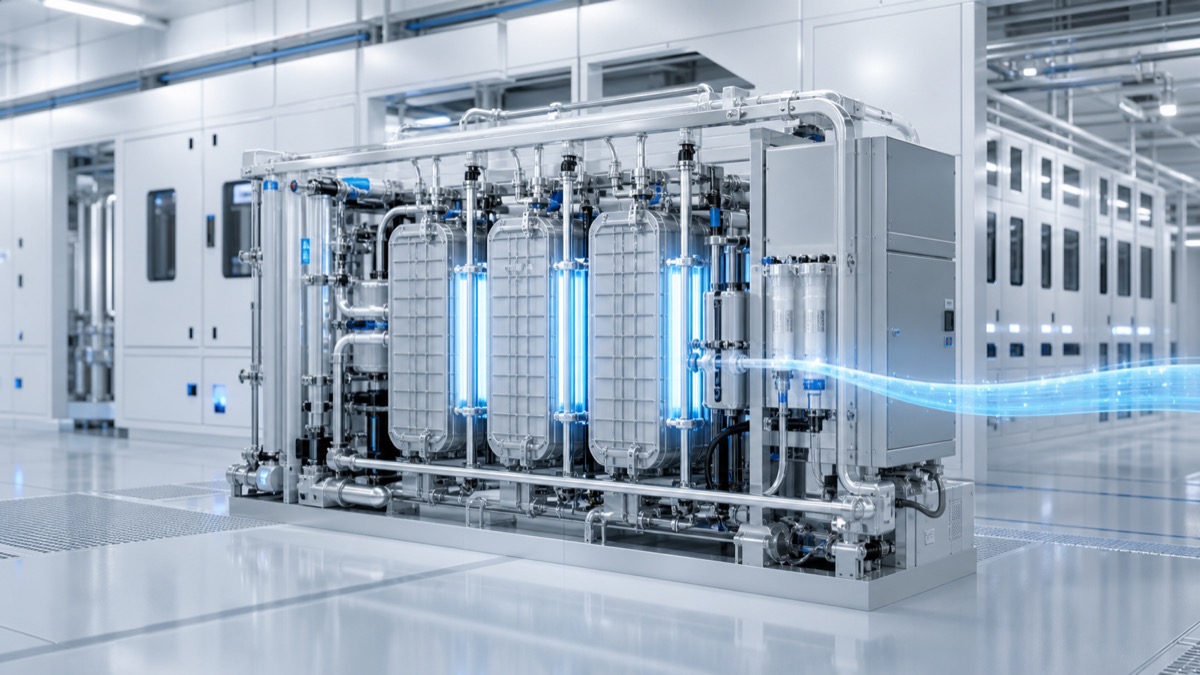
The EDI illustration is set in a clean UPW utility environment rather than a heavy industrial skid. That difference matters: the article is about reducing stack resistance and current waste while holding 18.2 MΩ·cm quality, so the visual emphasizes compact cell stacks, clean piping, power electronics, and stable polishing-loop instrumentation rather than bulk contaminant removal.
Limits and honest boundaries
While this approach's advanced EDI offers substantial improvements, its optimal performance is contingent upon robust pre-treatment and careful operational management. Neglecting these aspects can severely degrade performance and compromise the promised energy savings:
- Inadequate Pre-treatment: High levels of hardness (e.g., Ca²⁺, Mg²⁺), heavy metals, or colloidal silica entering the EDI stack can lead to scaling on membranes or resin fouling, increasing resistance and power consumption. Total Hardness (as CaCO₃) should typically be below 0.1 mg/L, and often undetectable for advanced UPW.
- Organic Fouling: Organic compounds, even at low ppb levels, can irreversibly foul ion-exchange resins and membranes, reducing ion transport efficiency and necessitating more frequent chemical cleaning, impacting uptime and cost. Total Organic Carbon (TOC) should ideally be below 5 ppb for EDI feed.
- Particulate Contamination: Fine particulates can plug flow channels and abrade membranes or resins, leading to non-uniform flow and localized resistance increases. Silt Density Index (SDI) for EDI feed should typically be < 3.
- Dissolved Gases: High concentrations of CO₂ in the feed, if not adequately removed by a degasifier or forced-air degassifier prior to EDI, will consume ionic capacity in the dilute compartment, increasing the electrical load and potentially reducing permeate resistivity.
- Temperature Fluctuations: Significant variations in feed water temperature affect resin kinetics, membrane permeability, and water resistivity, leading to unstable performance if not compensated by intelligent control.
- Improper Voltage/Current Management: Operating too far above the limiting current density can cause water splitting, leading to pH shifts, scaling, and reduced current efficiency. Operating too low can compromise product water quality.
Related equipment & product lines
These categories typically support the approach above—open any line to compare brands and models.
- Ion Exchange ResinsCation/anion and mixed bed resin solutions for demineralization and polishing.View category →
- RO MembranesReverse osmosis membrane elements for municipal and industrial desalination.View category →
- Instrumentation & SensorsOnline measurement and control: flow, level, pressure, and water-quality sensors indexed from the Lenntech instrumentation hub.View category →
For a closer review, use the engineering inquiry form to share feed, capacity, target, and project stage. Submission does not constitute a completed design or performance commitment.