Illustrated guide · Equipment cutaway
How does a filter press turn sludge into filter cake?
Follow hydraulic clamping, pumped filling, cloth retention, outside-in cake growth, filtrate drainage, optional membrane squeeze, discharge and fault diagnosis through one batch pressure-filtration cycle.
Direct answer
Direct answer
A plate-and-frame or recessed-chamber filter press is not a hydraulic ram that directly squeezes sludge. Its closing cylinder first clamps and seals a plate pack. A feed pump then drives conditioned sludge into closed chambers between adjacent plates. Pressure forces liquid through the filter cloth and through the plate's support pips and drainage channels to the filtrate ports. Solids larger than the effective media openings—or captured after an initial bridge layer forms—remain on the cloth. Cake grows from both cloth faces toward the chamber centre. As cake thickness and compressible resistance rise, filtrate flow falls at the same feed pressure. A recessed-chamber press normally ends feed after the chamber is full and endpoint flow is reached. A membrane press may then apply OEM-specified water or air behind flexible membranes to compress an already formed cake; this stage is not present on every press. Feed, squeeze and air services must be stopped, isolated and proven depressurized before the pack opens for cake discharge and cloth cleaning. Final dry solids depend on feed solids, flocculation, particle/colloid properties, compressibility, cloth, cake thickness, feed profile and endpoint—not pressure alone. Bound and intracellular water are especially resistant to mechanical removal. Diagnose with synchronized feed pressure/flow, individual or manifold filtrate flow/turbidity, cycle time, cake thickness/mass/dry solids, polymer dose, clamp status, leaks, uneven cakes and cloth condition.
Four conditions produce a complete, releasable cake and clear filtrate
Clamping, feed distribution, cloth/cake resistance and conditioning must agree; a mismatch becomes spray leakage, uneven fill, wet cake or long cycles.
Align and clamp the plate pack first
Plates, cloth sealing margins and head/tail plates must be clean, flat and ordered correctly. Hydraulic closure only resists chamber force and keeps the seal; trapped cake, creased cloth or low clamp force can cause slurry blowout.
Fill along an approved feed-pump profile
Use high initial flow to fill voids, then control flow/pressure as backpressure rises without exceeding plate, piping or closure ratings. Blocked centre/corner ports cause incomplete chambers.
Retain solids while draining filtrate
Cloth fibre, weave and permeability must match particles and chemistry. Early filtrate can be slightly cloudy before a precoat-like layer forms, but stable filtrate should clear. Blinding, holes, folds and wrong installation cause high resistance, turbidity or leaks.
Condition sludge and define a real endpoint
Polymer must create strong, drainable flocs: too little loses solids, too much makes a slimy blinding layer. Use flow, pressure, filled volume and test data for endpoint; more time or pressure often yields little extra water.
An industrial press combines a clamped plate pack, cake discharge and conveyor
White cloths cover the plates; the hydraulic cylinder drives the moving head against the fixed head. At the end of a batch the pack opens and cakes fall to the conveyor below.
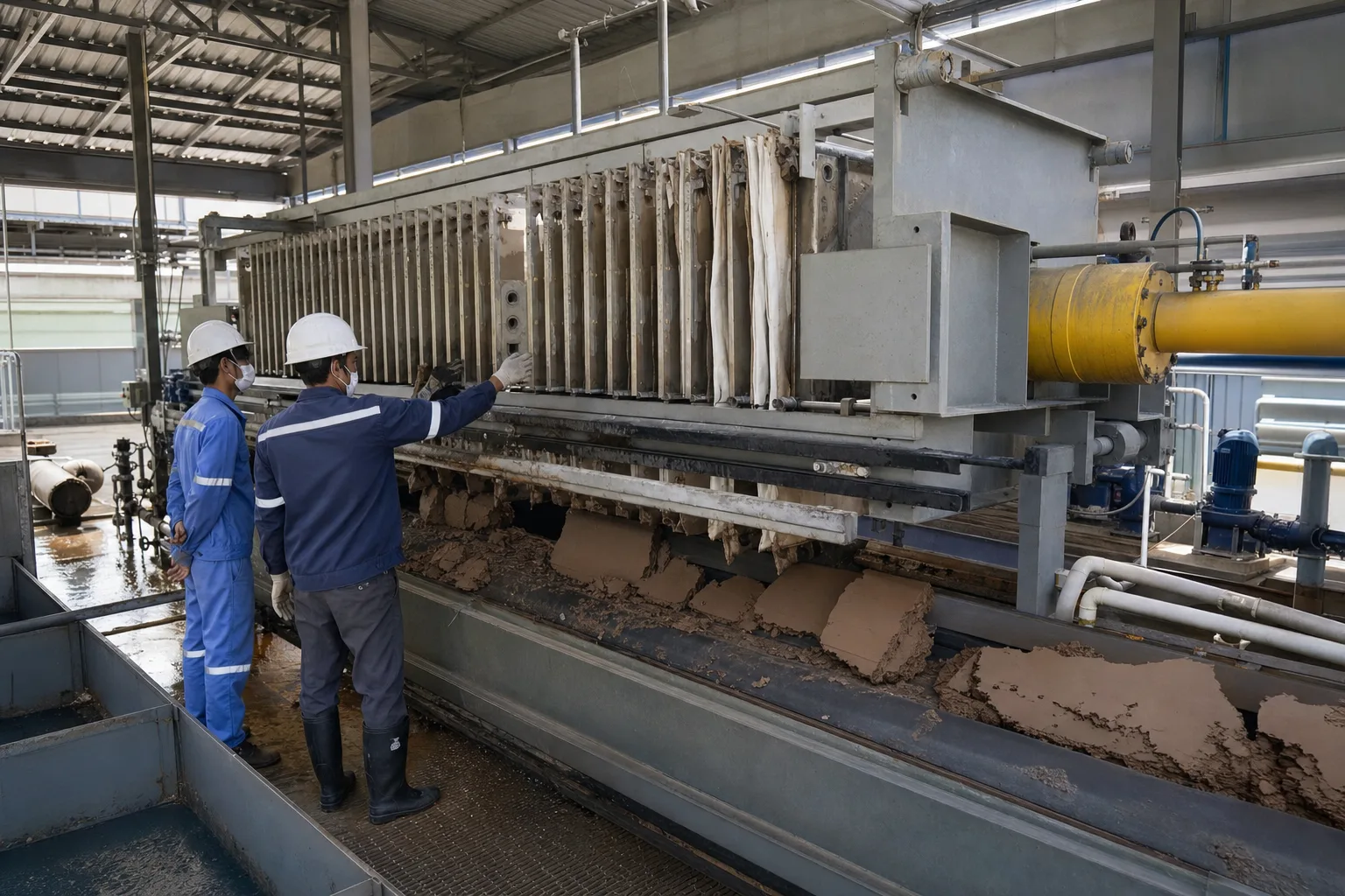 11Plate pack and filter cloths22Moving head / clamped pack33Hydraulic closing cylinder44Cake drop and conveyor
What to identify
- 1Plate pack and filter cloths
- 2Moving head / clamped pack
- 3Hydraulic closing cylinder
- 4Cake drop and conveyor
What this proves
The cylinder clamps the pack; it does not directly dewater each cake. Feed-to-filtrate differential pressure moves water through cloth, while the frame carries the sum of all chamber forces.
Field check
Verify rated feed and clamp pressure/position, plate count/order and clean sealing margins. From outside the safeguarded zone, trend interplate spray, frame movement and hydraulic retreat during feed.
Open plates reveal the chamber, feed passage, drainage face and separate filtrate outlets
Opposing recesses form a chamber. Sludge enters through a continuous port; cloth lies on a pip/drainage field, and filtrate exits through lower outlets.
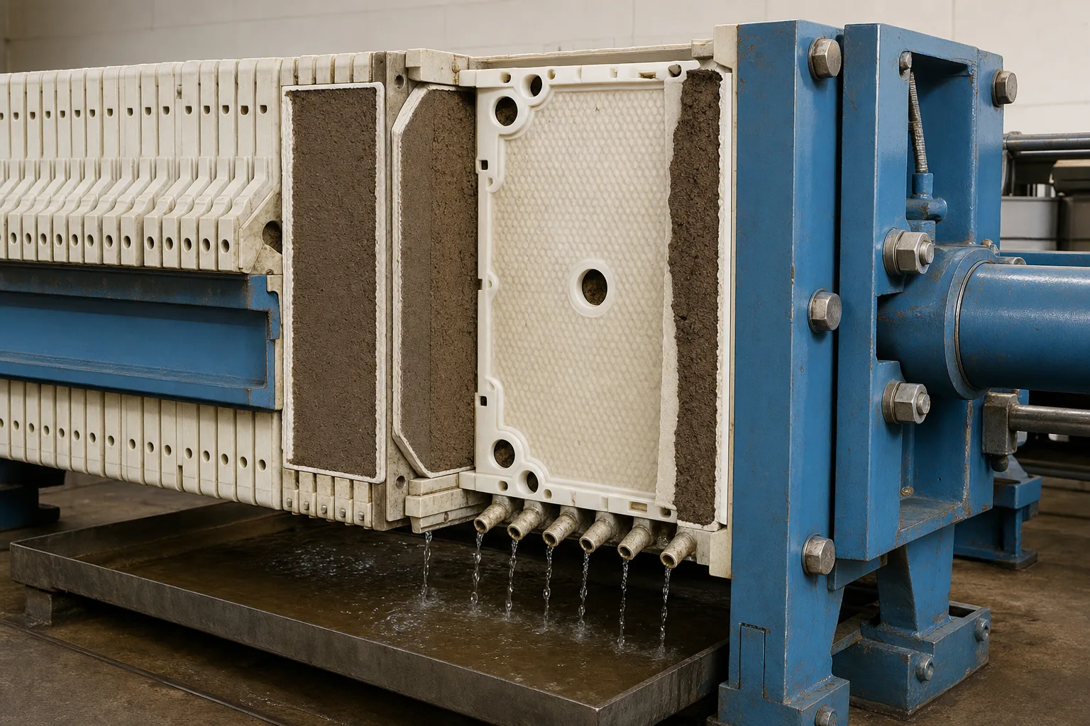 11Recess and formed cake22Centre/corner feed passage33Drainage field behind cloth44Individual filtrate outlets
What to identify
- 1Recess and formed cake
- 2Centre/corner feed passage
- 3Drainage field behind cloth
- 4Individual filtrate outlets
What this proves
The cloth divides two paths: solids stay in the chamber while filtrate flows through the backing channels. Open outlets can identify one damaged cloth; closed-manifold presses rely on zone design and turbidity.
Field check
Confirm feed/corner holes line up, cloth openings are correct and outlets/manifold are clear. Compare start time, flow and clarity; persistent cloudiness at one outlet identifies a plate pair to inspect.
A transparent test press shows cake growing from cloth toward the chamber centre
A controlled pump feeds suspension. Solids first bridge on both cloth faces and thicken inward; cylinders below collect filtrate for volume and clarity comparison.
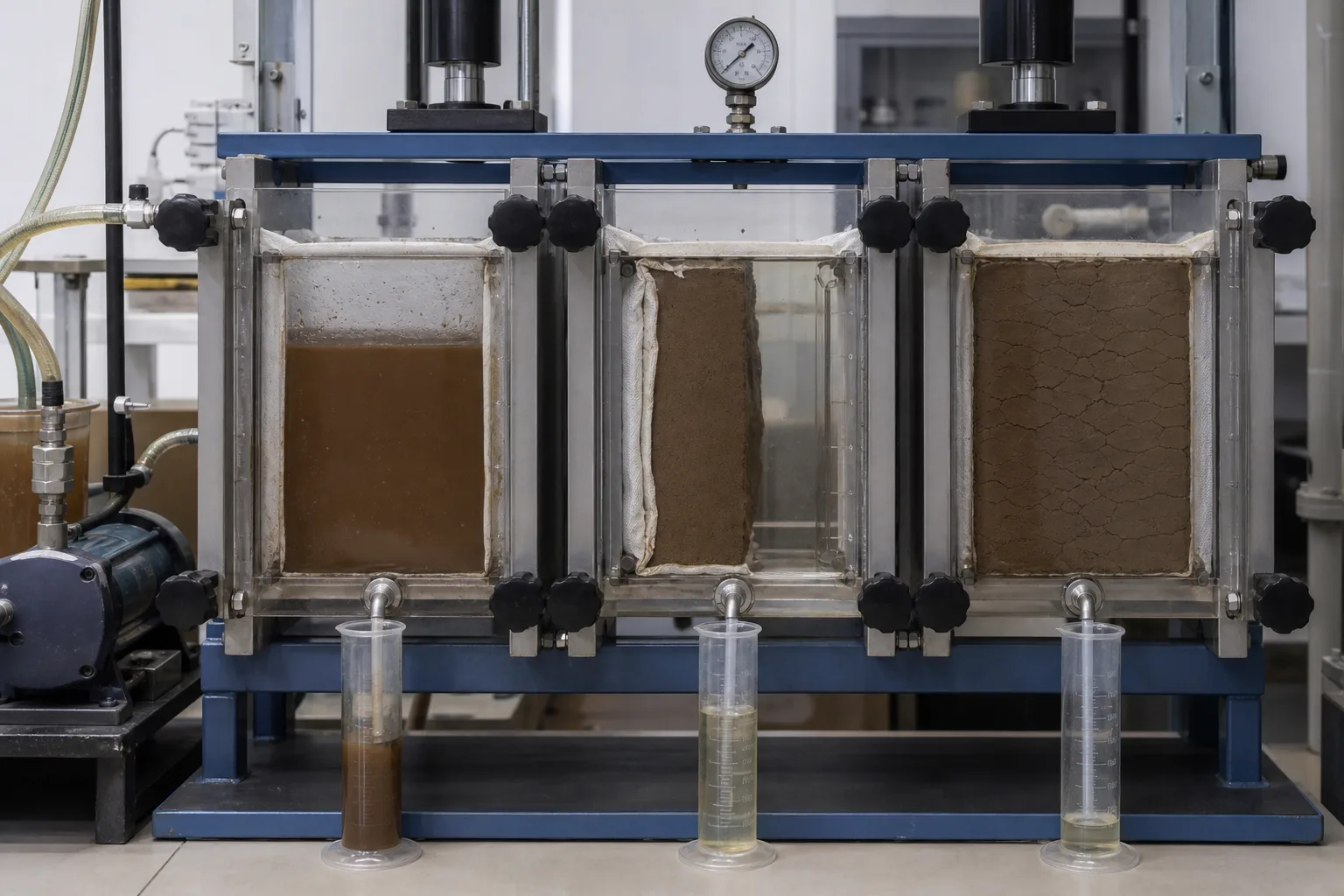 11Controlled feed pump22Sludge suspension33Cake growing from both faces44Filtrate volume and clarity
What to identify
- 1Controlled feed pump
- 2Sludge suspension
- 3Cake growing from both faces
- 4Filtrate volume and clarity
What this proves
Initial area is open and flow is high. Growing cake becomes the main filter and resistance. Compressible sludge closes its pores at high pressure, so drainage need not rise in proportion to pressure.
Field check
For a trial or first batch, log feed P/Q, cumulative filtrate and turbidity versus time; measure cake thickness and dry solids by position. Set ramp and endpoint from the curve, not a timer alone.
Four chambers show how conditioning and cycle settings change cake and filtrate
The same rig shows unformed slurry, a complete releasable cake, a wet compressible cake, and a cracked/residual cake; filtrate and cake samples expose different outcomes.
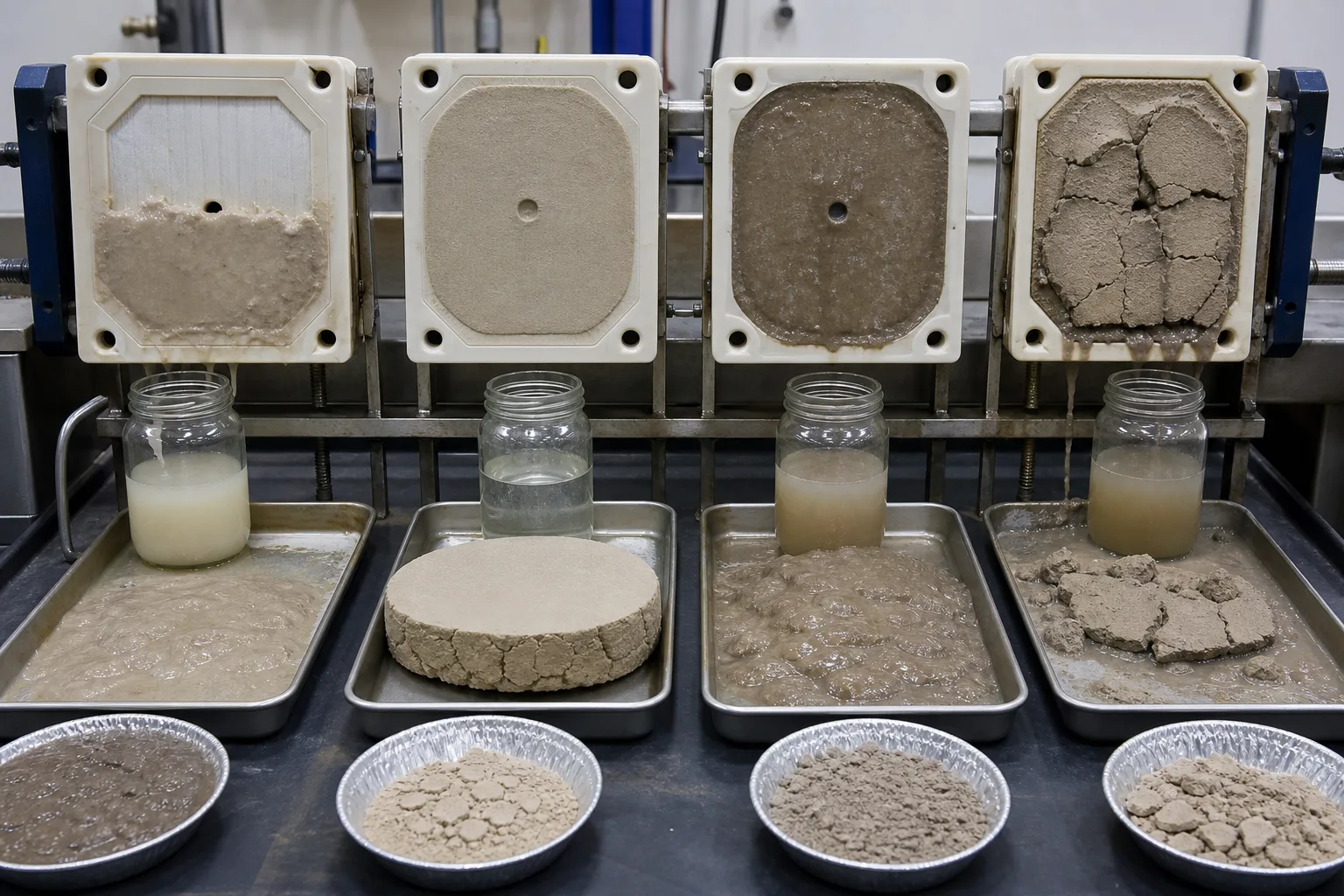 11Slurry / no stable layer22Uniform releasable cake33Wet compressible cake44Cracked, residual or uneven cake
What to identify
- 1Slurry / no stable layer
- 2Uniform releasable cake
- 3Wet compressible cake
- 4Cracked, residual or uneven cake
What this proves
Cracks do not prove maximum dryness; they may reflect shrinkage, excessive air drying or discharge. Clear filtrate also does not prove the highest cake solids. Optimize capture, solids loading, cycle and dryness together.
Field check
On the same feed compare solids, pH/temperature, polymer type/active dose, mixing, P–Q curve and cake solids. Retain cloth and plate position IDs so a local fault is not mistaken for a chemistry problem.
Maintenance exposes filter cloth, plate, feed-port and stored-energy hazards
Removed cloths and textured plates lie beside an open pack; the hydraulic end is padlocked. Entry is allowed only after electrical, hydraulic, pneumatic and process isolation.
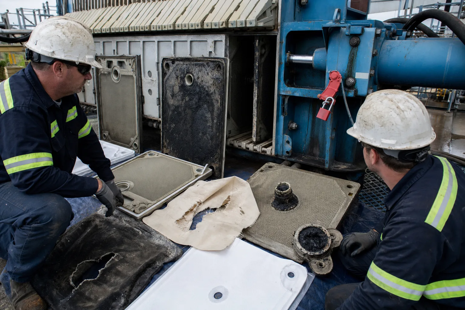 11Plate seal and drainage face22Removed torn/blinded cloth33Cylinder and moving head44Lockout and stored-energy isolation
What to identify
- 1Plate seal and drainage face
- 2Removed torn/blinded cloth
- 3Cylinder and moving head
- 4Lockout and stored-energy isolation
What this proves
Pinch points, hydraulic/pneumatic energy, trapped slurry and automatic shifters can crush or inject fluid. E-stop is not zero energy; all feed, squeeze, air and hydraulic sources require isolation and verification.
Field check
Apply site LOTO and the OEM procedure. Prove gauges at zero, valves isolated and stored pressure released; secure moving parts and inspect guarding, light curtains/pull wires, limits, plates, cloth margins and hydraulic leaks.
Seven batch steps from dilute sludge to cake
Each stage has distinct energy, valve states and endpoints. Membrane squeeze, cake wash and air/core blow are optional engineered stages, not universal instructions.
1 Condition
Thickened sludge + polymer → drainable floc
Improve capture and drainage instead of forcing colloids directly onto cloth.
2 Close
Cylinder → moving head → clamped pack
Align and seal chambers with force sufficient to resist feed pressure.
3 Fill/filter
Feed pump → feed port → chamber → cloth
Fill voids, then use differential pressure to drain water and retain solids.
4 Reach endpoint
Cake thickens → resistance rises → filtrate falls
Use P/Q, volume and filtrate condition to prove filling rather than time alone.
5 Optional finish
Membrane squeeze / wash / core or air blow
Apply only to a designed press under its OEM sequence and limits.
6 Depressurize/open
Stop/isolate → zero pressure → release/shift
Remove process, pneumatic and hydraulic energy before discharge access.
7 Discharge/clean
Open → cake drop → inspect/wash → close
Restore drainage and sealing area; record cake yield and bad plate positions.
Verify closure, separation, conditioning and safety separately
The same wet cake can originate in feed, polymer, cloth, pump or plate pack; pressure is not a universal cure.
Closure/frame
- Normal duty
- Align and seal plates and carry axial chamber force
- Typical failure
- Clamp loss, plate misalignment/crack, dirty seal, shifter/limit fault
- Evidence
- Clamp P/position, plate order/gaps, leak location, frame movement, interlock test
Feed/filtrate
- Normal duty
- Fill chambers evenly and create safe filtration differential
- Typical failure
- Pump/valve mismatch, blocked feed core, maldistribution, blocked outlet/backpressure
- Evidence
- Feed P/Q/volume, valves, individual Q/turbidity, fill time, pump curve
Cloth/cake
- Normal duty
- Capture solids, support layer and drain liquid
- Typical failure
- Blinding, tear/fold/reversal, sticky or compressible/uneven cake
- Evidence
- Cloth ID/permeability, outlet turbidity, cake thickness/mass/DS, pre/post-clean cycle
Sludge/conditioning
- Normal duty
- Make a drainable, releasable floc that meets disposal needs
- Typical failure
- Solids/size/temp change, under/overdose, floc shear or incompatibility
- Evidence
- Feed TS/VS, particle/floc test, active dose, bench press, filtrate SS and cake result
Close the material balance: feed dry solids ≈ cake dry solids + filtrate suspended solids; feed water ≈ filtrate water + residual cake water. Feed, membrane and air pressures and safety interlocks must come from the actual OEM, plate material, cloth and sludge test—not another press.
Align three trend groups on one batch timeline
Pressure, flow and safeguards
Clamp pressure/position, feed P/Q/volume, total/individual filtrate flow, optional squeeze/blow pressure and time, valves, E-stops and interlock state.
Filtrate, cake and cycle
Filtrate turbidity/SS and clearing time, endpoint flow, fill/finish/open/discharge time, cake thickness/uniformity/wet mass/dry solids and cloth release.
Feed, chemistry and resources
Feed flow, TS/VS, pH/temperature, polymer type/active concentration/dose per dry solids, cloth-wash water, energy, recovered solids and filtrate destination.
Diagnose with pressure–filtrate–cake–position
- Signal
- Pressure rises immediately, little filtrate, wet or absent cake
- Suspect first
- Blocked feed/drain path, severe cloth blinding, or overconditioned compressible gel
- Next step
- Stop and depressurize safely; separate pipe and cloth checks, compare clean permeability and bench dose—do not raise pressure
- Signal
- One filtrate outlet stays cloudy while others clear
- Suspect first
- Torn/folded/misaligned cloth or damaged drainage face at that plate
- Next step
- Map outlet to plate, complete cycle, LOTO and inspect/replace; check recurring sharp-particle damage
- Signal
- Sudden slurry jet between plates or continuous corner leak
- Suspect first
- Creased/dirty cloth edge, misaligned/cracked plate, clamp loss or excessive feed pressure
- Next step
- Stay outside spray zone, stop feed remotely and depressurize; inspect the exact plate, seal and clamp hold—never tighten live
- Signal
- Low endpoint flow but cakes remain uneven, sticky or partly wet
- Suspect first
- Maldistribution, incomplete fill, feed/dose variation, cloth blinding or timer-only endpoint
- Next step
- Map cake thickness/DS and outlet flow by position; restore uniform fill before changing endpoint or squeeze
Four common misconceptions
The hydraulic cylinder squeezes sludge dry
It mainly clamps the pack; the feed pump creates filtration pressure, and only membrane designs add a squeeze stage.
More pressure and time always make a drier cake
Compressible cake closes its pores and bound water remains; marginal water removal can collapse.
Clear filtrate proves optimum operation
Also measure cake solids, capture, cycle, polymer and area productivity; a tight cloth can be clear but slow.
Opening is safe as soon as the feed pump stops
Chambers, core, membranes, air and hydraulics may retain energy; isolate, release and verify zero.