Illustrated guides · Physicochemical treatment
Why is a larger settling tank not always better?
Settling depends on particle settling velocity versus upward flow per unit surface area, plus uniform inlet distribution, calm separation, even outlet withdrawal and timely sludge removal. More total area only lowers nominal loading.
Direct answer
Direct answer
For ideal discrete settling, capture depends mainly on particle settling velocity compared with surface overflow rate Q/A, not simply on greater depth or volume. Real basins add flocculent settling, inlet momentum, density currents, wind, outlet draw, scraper operation and sludge-blanket effects, so effective surface area, peak train flow, solids loading and sludge withdrawal matter. Blindly enlarging a basin can create low-flow dead zones, algae, septic or gasifying sludge, longer collector spans and higher maintenance. Poor inlet and outlet design can still let water take a short path through a very large tank, giving long nominal but short effective residence. Good clarification balances area, depth, hydraulics, collection, redundancy and controllability.
Four scales determine whether a clarifier is truly adequate
Geometry provides nominal capacity; particle fate is governed by flow, settling, flow paths and solids removal.
Surface loading matches target settling velocity
Q/A is the characteristic upward hydraulic velocity. Use peak flow per operating basin and real effective area; feedwells, launders and failed zones are not free capacity.
Inlet momentum is dissipated and distributed
Jets, unequal distribution and density differences can drive solids toward the outlet. Feedwells and baffles must distribute flow horizontally and vertically.
Outlet withdrawal is not locally concentrated
High local weir loading or uneven weir elevation creates upflow near the outlet and can carry floc that was nearly settled.
The sludge layer is controlled and removed
Settled solids consume depth and can compact, turn septic, gasify or be disturbed. Larger collectors can also add span, dead-corner and long-retention risks.
A large site footprint does not mean every square metre is effective settling area
The aerial view combines inlet works, a mechanically equipped unit, several large basins and low-motion or algae-affected surfaces, separating total, online and effective area.
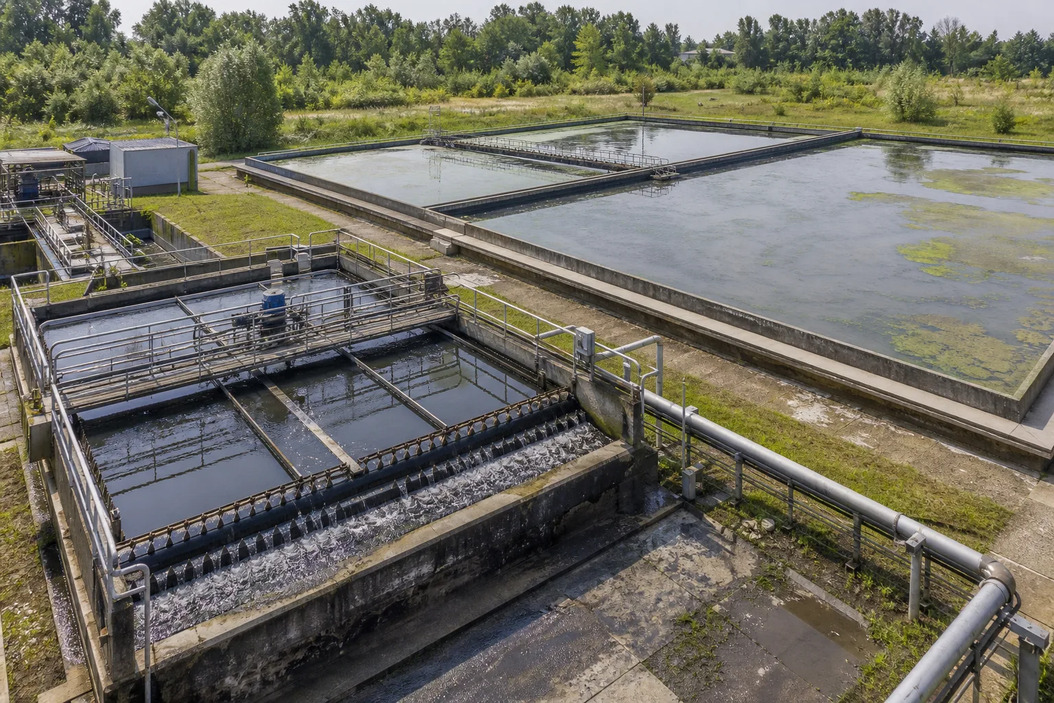 11Inlet/distribution works22Online mechanical clarifier33Large low-motion zone44Basin outlet/connection path
What to identify
- 1Inlet/distribution works
- 2Online mechanical clarifier
- 3Large low-motion zone
- 4Basin outlet/connection path
What the image proves
Standby or offline tanks, inlet/outlet structures, algae-covered zones and severe short-circuit paths cannot all count as effective area. Unequal train flow can overload one basin despite generous plant-wide area.
How to verify on site
List geometry, online state, measured train flow and weir length for every basin; calculate train Q/A and compare levels, effluent solids, sludge, algae/scum and collector state.
Capture is a competition between settling velocity and upward/forward water motion
A high-energy influent enters at left, floc settles through the center, clearer water forms above and a sludge layer collects below. Real flocculation and hindered settling complicate the ideal path.
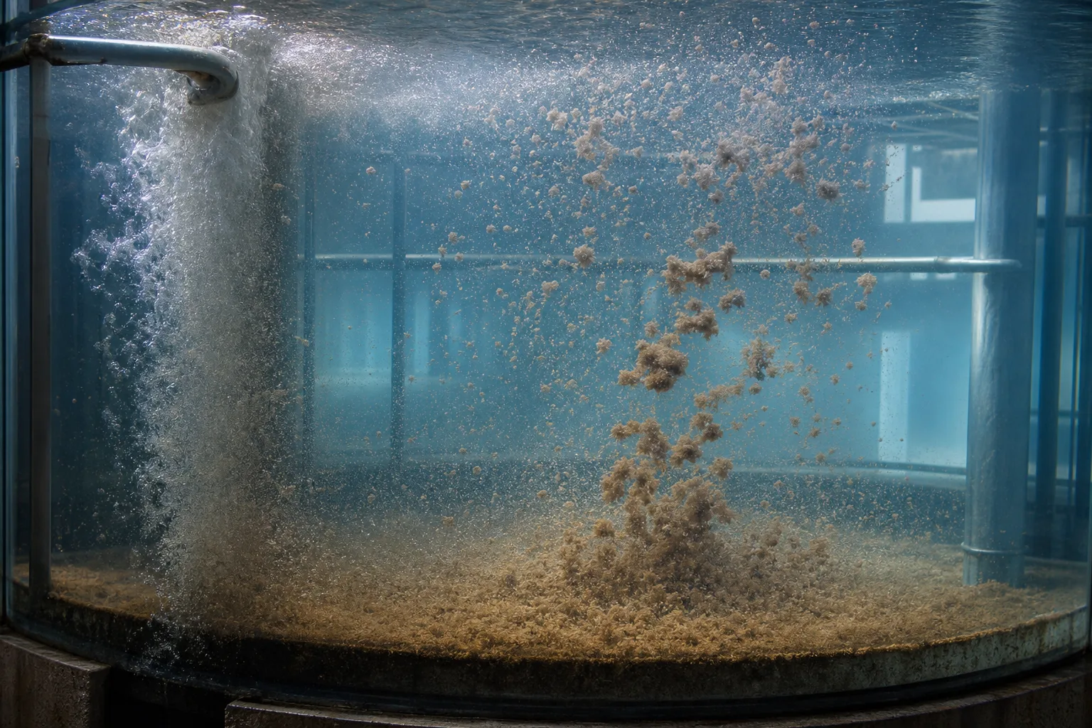 11High-energy solids feed22Fines and primary floc33Effective settling zone44Bottom sludge layer
What to identify
- 1High-energy solids feed
- 2Fines and primary floc
- 3Effective settling zone
- 4Bottom sludge layer
What the image proves
Ideal theory uses surface loading for discrete particles, but real floc velocity changes with size, density, concentration and shear. More detention helps only with acceptable hydraulics and sludge management; it cannot replace area or feed conditioning.
How to verify on site
Run column or jar settling observations, record feed TSS/particles, temperature and floc strength, and calculate peak train surface loading rather than reporting design detention time alone.
An effective basin links inlet energy control, settling, even withdrawal and sludge removal
The cutaway shows feed/baffle, a calm separation zone, distributed outlet weirs and a bottom collector moving sludge to withdrawal.
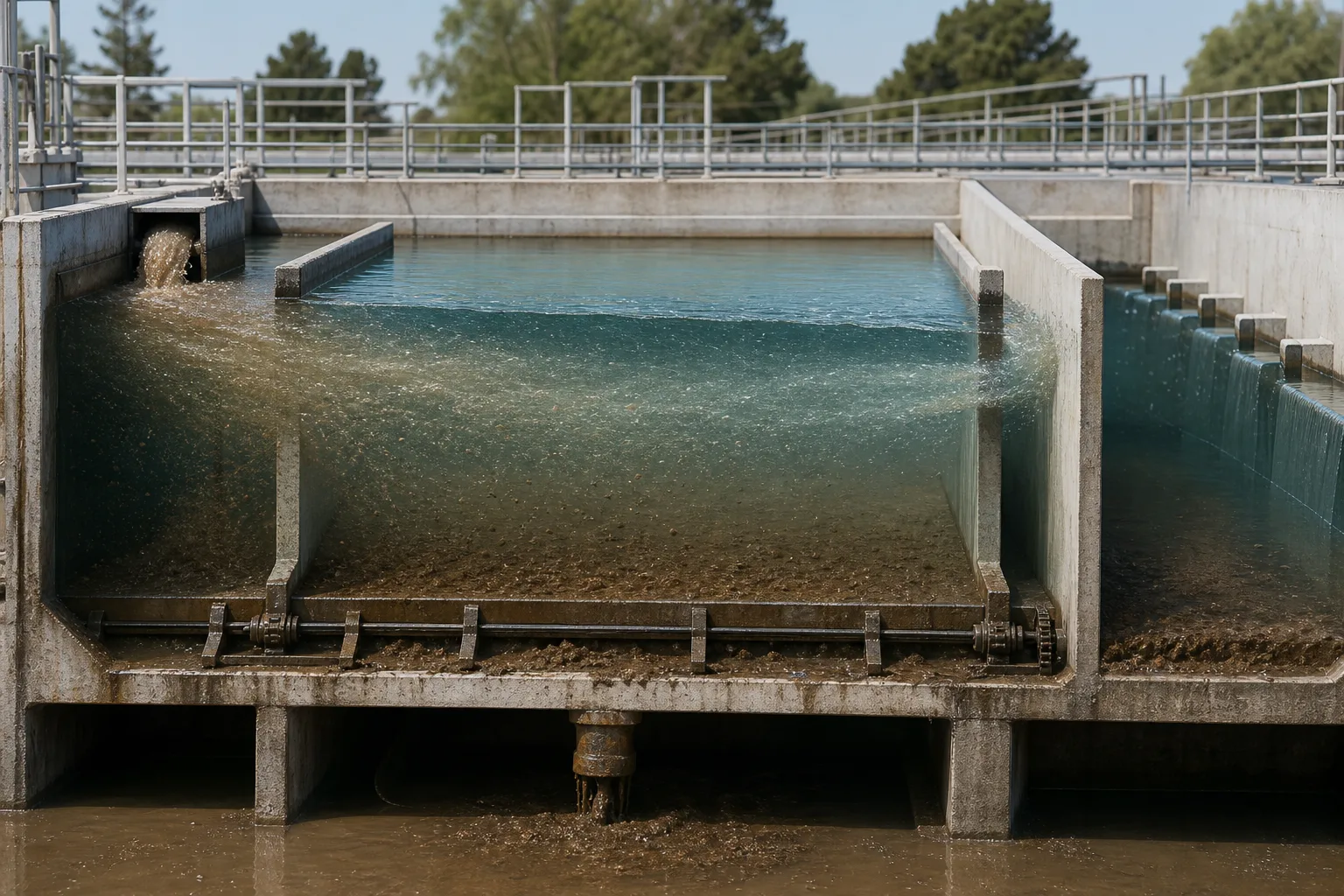 11Inlet and energy baffle22Calm effective zone33Distributed outlet weirs44Collector and sludge outlet
What to identify
- 1Inlet and energy baffle
- 2Calm effective zone
- 3Distributed outlet weirs
- 4Collector and sludge outlet
What the image proves
Length or diameter is only the shell. A jet over the baffle, uneven weirs, stopped collectors or filled hoppers reduce effective area, lift the blanket or scour solids into the effluent.
How to verify on site
Inspect inlet velocity/baffles and water-level difference, measure head over weirs by segment, map sludge depth, and trend withdrawal concentration/flow and scraper torque/current.
At equal flow, undersized, matched and oversized-but-unmanaged tanks differ
Three transparent units show high loading, a balanced separation/withdrawal condition and a large tank with retained sludge and poorer hydraulics. Effluent samples decide performance.
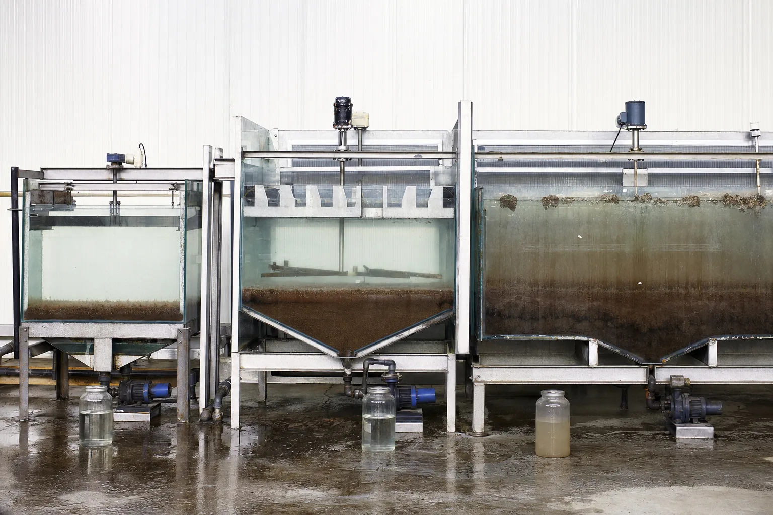 11Undersized/high loading22Matched settling/removal33Oversized with retained sludge44Three effluent samples
What to identify
- 1Undersized/high loading
- 2Matched settling/removal
- 3Oversized with retained sludge
- 4Three effluent samples
What the image proves
A small basin loses solids at high loading; moderate extra capacity buffers peaks; excessive low-load volume with poor withdrawal can promote dead zones, sludge aging, gas flotation and algae. The optimum is a controllable life-cycle window.
How to verify on site
Compare operating-basin combinations using Q/A, residence distribution, blanket age/depth, effluent TSS, underflow concentration, energy and maintenance; do not infer cause from area alone.
Tracer testing reveals short circuits, recirculation and dead zones hidden by nominal volume
A tracer band in a circular clarifier, center feedwell, peripheral launder, bridge and sampling operator represent a field hydraulic test. Tracer choice and discharge must be approved.
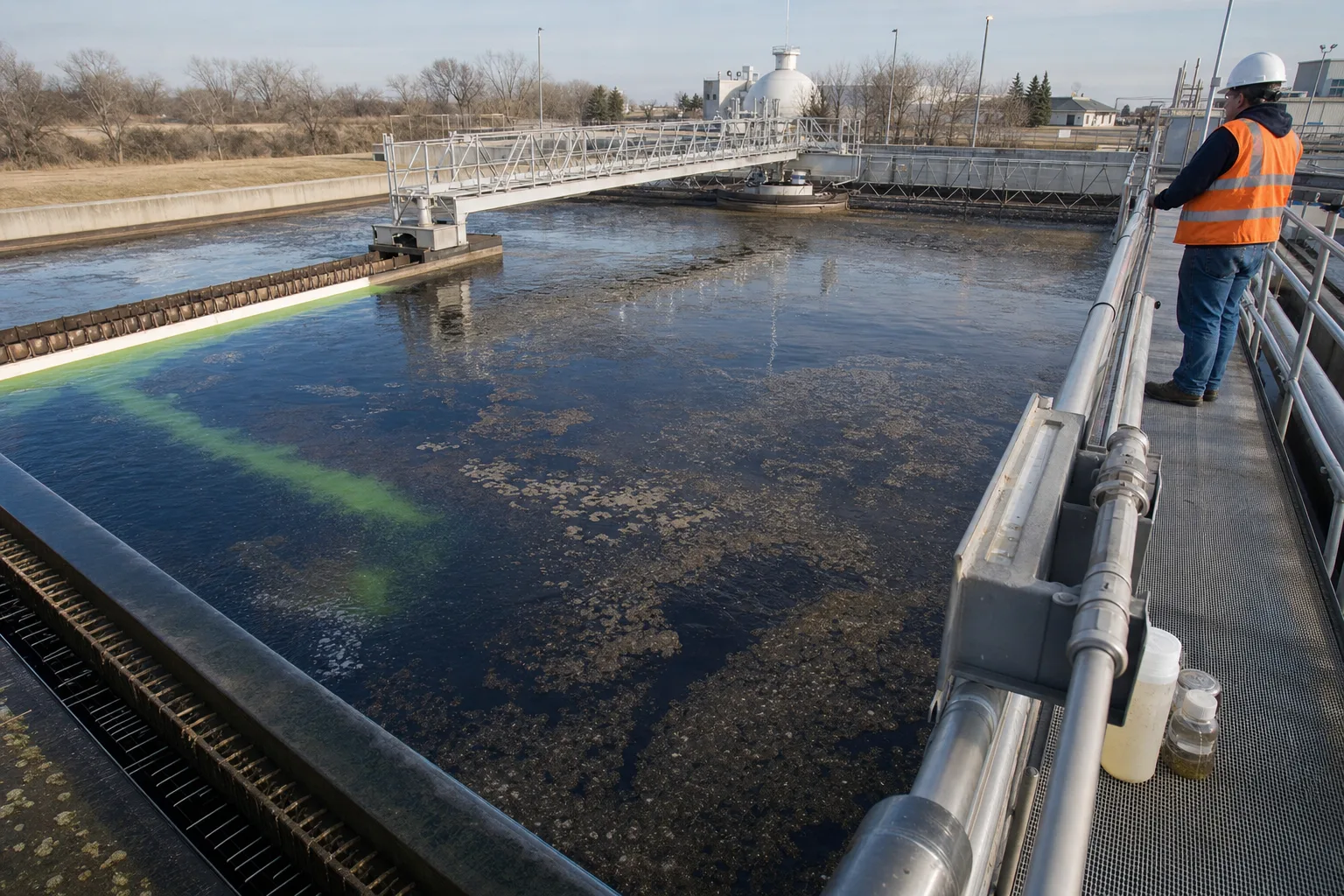 11Center feedwell/distribution22Tracer main flow path33Peripheral weir/launder44Multi-point sampling curve
What to identify
- 1Center feedwell/distribution
- 2Tracer main flow path
- 3Peripheral weir/launder
- 4Multi-point sampling curve
What the image proves
An early outlet peak indicates a fast path; a long tail suggests recirculation or exchange with dead zones. Two tanks with the same average residence can have very different short-circuit fractions and effective volumes.
How to verify on site
Where permitted, use salt, fluorescent or dye tracer and build concentration-time curves at multiple outlets; combine flow, level, temperature and wind, then compare before/after baffle or weir changes.
Six steps from inlet to clarified effluent
Tank size has engineering meaning only inside this pathway.
1 Split flow
Plant flow → online basins
Sets real train Q/A and peak load.
2 Dissipate inlet
Jet → low-velocity distribution
Reduce disturbance, bias and direct outlet paths.
3 Settle particles
Settling vs upward/horizontal velocity
Move target solids below the withdrawal path.
4 Collect sludge
Deposits → scraper/hopper
Prevent depth loss, gas and resuspension.
5 Withdraw evenly
Clear zone → distributed weirs
Limit local upflow and carryover.
6 Feed back
Effluent + blanket + hydraulics
Adjust online area, flow split and withdrawal.
What area, depth, hydraulics and sludge removal each solve
No single design number represents clarification capacity.
Effective surface area
- Primary duty
- Convert train flow to acceptable upward surface velocity
- Typical imbalance
- Peak overload, offline area counted, structures/short paths reduce area
- Field evidence
- Online area, train flow, peak Q/A and effluent particles/TSS
Depth and volume
- Primary duty
- Provide floc/settling buffer, blanket space and hydraulic stability
- Typical imbalance
- Too shallow is disturbed; excessive low-load volume can stratify or retain sludge
- Field evidence
- Residence distribution, temperature/velocity, blanket and gas/float
Inlet/outlet hydraulics
- Primary duty
- Dissipate and distribute feed, then withdraw evenly
- Typical imbalance
- Jets, density/wind currents, uneven weirs or local high loading
- Field evidence
- Tracer, weir head, level, temperature/conductivity and surface paths
Collection/withdrawal
- Primary duty
- Remove deposits and maintain a controlled blanket
- Typical imbalance
- Stopped collector, corners, low/high withdrawal, blockage or scour
- Field evidence
- Blanket map, torque/current, underflow flow/solids, age and floating sludge
These are general hydraulic and solids-separation boundaries. Drinking-water coagulation basins, primary clarifiers and activated-sludge secondary clarifiers also depend on floc properties, fermentation, blanket compression and solids flux; one surface-loading value cannot be transferred across all cases.
Align three evidence groups
Hydraulics and online area
Plant/train flow, online units, effective surface area, average/peak Q/A, levels, head over weirs, bypass/recycle and peak duration.
Particles and sludge
Influent/effluent TSS, turbidity or particles; settling, blanket profile, underflow flow/solids, collector status, float/gas and algae.
Effective flow pattern
Tracer arrival/peak/tail, temperature/conductivity profiles, inlet jet, surface motion, wind, baffles/weirs and basin-to-basin differences.
Why can a large basin still give poor effluent?
- Combined signal
- One outlet-weir segment turns turbid first while the rest stays clearer
- First suspicion
- Biased flow, uneven weir, local weir loading or short circuit
- Next action
- Map head/turbidity by weir segment, inspect distribution/baffles and run multi-point tracing before adding area
- Combined signal
- Flow is modest but blanket is deep, bubbles rise or sludge floats in sheets
- First suspicion
- Low withdrawal, collector dead zone or excessive sludge retention with gas/septicity
- Next action
- Map blanket, underflow flow/solids and torque; clear hopper/lines and shorten sludge retention
- Combined signal
- A storm or production peak causes immediate blanket loss, then recovery
- First suspicion
- Peak Q/A, transient hydraulic surge or inlet momentum exceeds capacity
- Next action
- Recalculate with peak train flow, verify equalization/split and peak duration, then inspect baffles/launders
- Combined signal
- Nominal detention is long, but tracer peaks early and has a long tail
- First suspicion
- Fast path and dead zones coexist; effective volume is far below geometry
- Next action
- Use density/wind evidence to locate paths, modify inlet/baffles/weirs and repeat the tracer test
Four common misconceptions
Deeper always settles better
Ideal discrete capture is governed mainly by Q/A versus settling velocity; depth affects hydraulics and sludge space but is not simply better.
Adequate design detention guarantees removal
Average V/Q hides short circuits and dead zones; residence-time distribution and flow paths matter.
Large total area prevents overload
Offline units, unequal flow and ineffective zones can still overload a train; use operating effective area and train flow.
Poor effluent means another tank is needed
If distribution, weirs, sludge or floc is the cause, a new basin can reproduce the same defect. Establish hydraulic and solids evidence first.