Illustrated guide · Equipment cutaway
How does an automatic control valve switch between filtration and backwash?
See how the controller, gearmotor, position feedback and piston/seal stack remap fixed inlet, outlet, drain and tank ports for service, backwash and rapid rinse.
Direct answer
Direct answer
An automatic multiport valve does not reverse the pump. A small motor and reduction drive move a piston, spool or ceramic disc to indexed positions, reconnecting the same fixed ports. In a common downflow filter, service connects inlet to the top distributor; water travels down through the bed and returns through the bottom distributor/riser to outlet. Backwash connects inlet to the riser, lifting water upward through and expanding the bed before dirty water leaves the tank top for drain. Rapid rinse restores downward flow but routes it to drain so the media can restratify and residual turbidity is kept out of product; only then does the valve return to service. Filter-only valves commonly use service, backwash and rapid rinse. Softener/regeneration valves may also add brine draw/slow rinse and brine refill, so one cycle diagram does not fit every valve. A controller may trigger from time, throughput, differential pressure or a remote input; position feedback confirms arrival before each step timer runs. Cleaning depends on more than minutes: drain-flow control, available pressure, media size/density, water temperature, tank diameter, bed expansion and drain capacity must match. Piston, rotary-disc, downflow/upflow and bypass designs differ; use the exact OEM flow diagram and program for the installed model.
Four conditions make a real flow-path change
Motor motion is not proof of correct water routing; position, isolation, backwash hydraulics and system interlocks need separate evidence.
The drive reaches every indexed position
Controller, gears, cam/shaft and sensor must move the valve member to its stop or encoded position. Binding, stripped gears or bad feedback can leave two paths partly open.
The seal stack isolates adjacent galleries
A piston with seals/spacers or moving/stationary ceramic discs selects ports. Wear, grit, swelling or wrong assembly creates internal cross-leakage among service, drain and optional brine paths.
Backwash flow cleans without carrying media out
The drain-flow control and dynamic pressure must deliver target expansion at current temperature. Too little channels the bed; too much loses media, damages distributors or overloads the drain.
Vessels, pumps and downstream demand are interlocked
Parallel vessels should not all backwash together. Pump, bypass, check valves, drain and downstream protection need a coordinated sequence beyond a single valve timer.
A multi-vessel system gives each tank a valve while sharing feed, product and drain headers
Motorized multiport heads sit on FRP media tanks; pressure gauges, isolation/bypass valves and headers tie each local position to the plant hydraulic state.
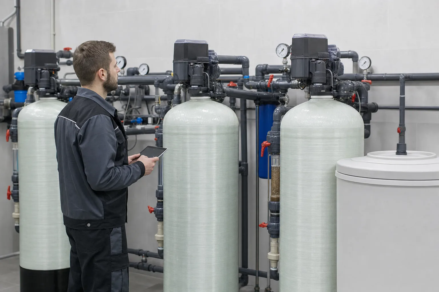 11Motorized multiport valve22FRP vessel and media bed33Feed/product/drain headers44Pressure, isolation and bypass
What to identify
- 1Motorized multiport valve
- 2FRP vessel and media bed
- 3Feed/product/drain headers
- 4Pressure, isolation and bypass
What this proves
The valve remaps one vessel; the system must still supply backwash water, accept drain flow and serve demand through the remaining tanks. Simultaneous backwash can starve expansion or overload the drain.
Field check
Map position, inlet/outlet pressure, flow and drain state per vessel. Trigger one unit and verify the others remain in service/interlocked; test pump speed, checks, bypass and drain under the limiting case.
The cutaway links the gear drive to a piston while the seal stack selects ports
A motor and reduction train drive the center valve member. White seals/spacers surround the piston; molded galleries lead to inlet, outlet, drain, tank and optional injector/brine circuits.
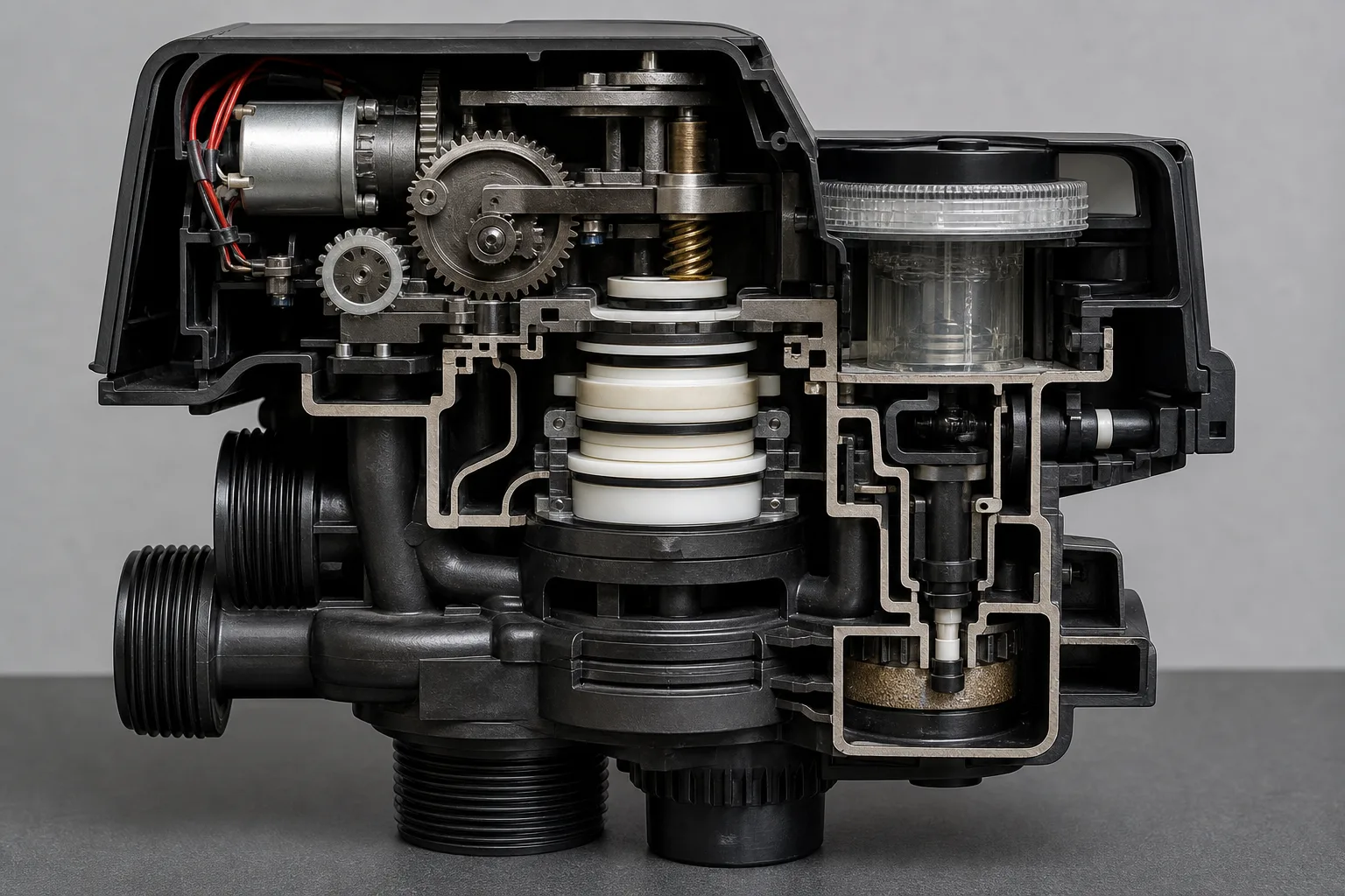 11Motor, reduction gears and positioning22Piston/spool and drive shaft33Seal-and-spacer stack44Ported body and injector/flow controls
What to identify
- 1Motor, reduction gears and positioning
- 2Piston/spool and drive shaft
- 3Seal-and-spacer stack
- 4Ported body and injector/flow controls
What this proves
Reversal is a port map inside the body. A short piston stroke closes one gallery and opens another; worn seals can cross-connect paths with no obvious external defect.
Field check
After power isolation and depressurization, verify free drive motion and position reset. Preserve seal/spacer order, inspect piston scratches, grit, swelling and O-rings, and never mix parts from another valve family.
Transparent stations make service, backwash, rapid rinse and optional regeneration paths visible
Clear valve heads and media columns show downflow service, upflow bed expansion, downward rapid rinse and a softener-specific chemical/slow-rinse option, while side flowmeters quantify each state.
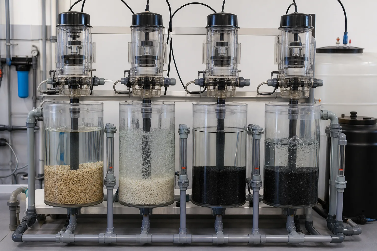 11Service: top in / bottom out22Backwash: bottom in / top to drain33Rapid rinse: downflow to drain44Optional brine/slow-rinse path
What to identify
- 1Service: top in / bottom out
- 2Backwash: bottom in / top to drain
- 3Rapid rinse: downflow to drain
- 4Optional brine/slow-rinse path
What this proves
A cycle name must match the actual ports and bed direction. Filter valves normally omit brine steps; softeners use an injector for brine draw. Upflow and custom programs alter order, so the display label is not a substitute for the OEM flow sheet.
Field check
Step manually and verify flow at inlet, outlet, drain and brine connection with clear hose or meters. Log starting and expanded bed height, stable drain flow and position arrival for every step.
Drain flow, turbidity and bed behavior tell more than a countdown
Parallel vessels show dirty early backwash, vigorous cleaning flow and late rapid-rinse discharge; clear drain sections and timed samples preserve hydraulic and water-quality evidence.
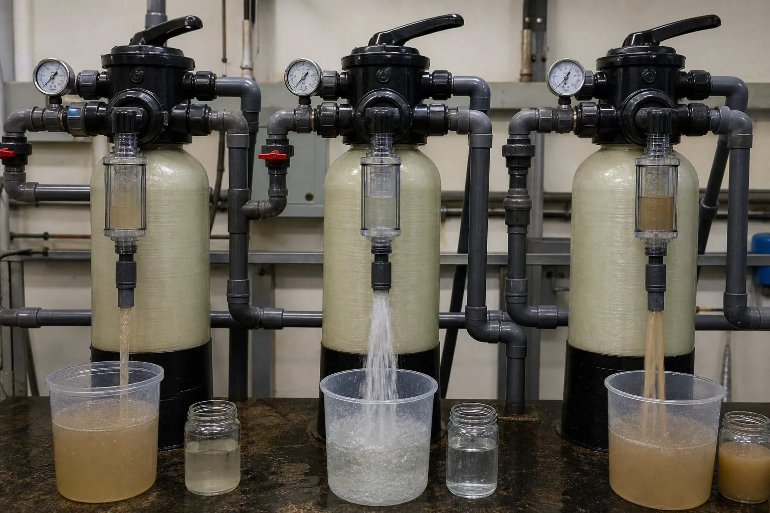 11Dirty early backwash discharge22Adequate upflow / bed agitation33Rapid-rinse residual fines44Timed drain sample / endpoint
What to identify
- 1Dirty early backwash discharge
- 2Adequate upflow / bed agitation
- 3Rapid-rinse residual fines
- 4Timed drain sample / endpoint
What this proves
A clear-looking drain is useful but not sufficient. Cleaning also needs target flow and expansion, recovered pressure drop and no media loss. Ending rapid rinse early sends residual turbidity to product; excessive time wastes water.
Field check
At early/mid/late backwash and final rinse, record drain flow/pressure, turbidity or particles, bed height and media carryover. Compare post-return vessel ΔP and product turbidity, then optimize by trend rather than one visual check.
Teardown separates drive, internal leakage, chemical draw and weak-backwash faults
Gears, piston and seals/spacers, injector/flow-control parts and body galleries lie beside measuring tools so wear, scale and debris can be assigned to a function.
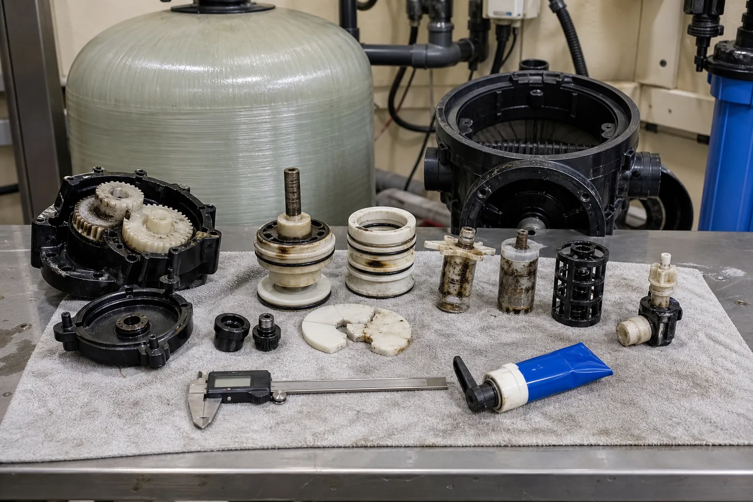 11Drive gears and cam housing22Piston, seals and spacers33Injector / drain-flow control44Valve galleries and dimensional check
What to identify
- 1Drive gears and cam housing
- 2Piston, seals and spacers
- 3Injector / drain-flow control
- 4Valve galleries and dimensional check
What this proves
No indexing points to drive/feedback; continuous drain or dirty product points to piston/seals; no brine draw points to injector, air leak or drain backpressure; weak backwash still requires measured flow and flow-control checks. One controller replacement does not fit every symptom.
Field check
Isolate, depressurize, de-energize and label piping before teardown. Match dimensions and parts to the diagram, clean without scratching sealing surfaces, then wet-test every position for real path and flow.
Six switching steps for a typical downflow filter
This is a functional sequence, not a universal piping diagram for every softener or upflow valve.
1 Trigger
Time/volume/ΔP/remote input → controller
Decide when to start based on loading and service demand.
2 Service
Inlet → tank top → bed↓ → riser → outlet
Treat water while trending vessel pressure drop and product.
3 Index
Motor → gear → valve member → sensor
Close/remap passages and confirm arrival before timing.
4 Backwash
Inlet → riser → bed↑ → tank top → drain
Expand/scrub media and export solids at a measured rate.
5 Rapid rinse
Inlet → tank top → bed↓ → drain
Resettle the bed and keep residual turbidity out of product.
6 Return
Re-index → outlet opens → verify
Confirm drain closure, recovered ΔP and acceptable first product.
Four subsystems determine switching, cleaning and safe return
Program, valve member, media hydraulics and plant piping need their own evidence.
Control/position
- Normal role
- Accept trigger, drive/index, confirm and sequence/alarm
- Failure
- Power/parameter fault, jammed gear, bad sensor, intermediate stop
- Evidence
- Position/time, codes, manual cycle, shaft/cam, output and remote/interlock state
Valve member/seals
- Normal role
- Create exclusive routes among inlet, outlet, drain, tank and optional brine
- Failure
- Scratched piston, worn/reversed seals, grit in discs, cross-leak
- Evidence
- Port flow by position, static leak, continuous drain, wear and assembly order
Bed/distributors
- Normal role
- Treat uniformly, expand uniformly and retain media
- Failure
- Channeling, cementing, under/overwash, media loss, broken distributor
- Evidence
- Bed height, flow, ΔP recovery, drain media, first-product turbidity and inventory
Pump/piping/drain
- Normal role
- Supply wash flow, control backpressure and maintain remaining service
- Failure
- Low pressure, restricted drain, simultaneous wash, hammer, bypass/check fault
- Evidence
- Dynamic P/Q, pump/VFD, drain level, interlock log, sequence and transient trend
Do not copy a backwash rate or expansion target from this page. Media size, uniformity, density, depth, water temperature/viscosity, vessel diameter, distributors and OEM limits control the result. Calculate from the media/valve curves and verify actual bed height and media carryover.
Keep three evidence groups on one timeline
Position and sequence
Record trigger, step start/end, command and feedback position, travel time, fault codes, manual skips and remote/interlock state. Separate a command from a hydraulically completed switch.
Flow, pressure and bed
Measure actual service/backwash/rinse flow, inlet/outlet/drain pressure, vessel ΔP, temperature, starting/expanded bed height, drain backpressure and media carryover.
Drain, product and return
Sample staged drain turbidity/particles, final rinse and first product; compare vessel ΔP and run length before/after cleaning.
Use signal combinations, not controller reboots
- Signal
- Display says backwash, but the bed does not expand and drain flow is low
- First suspicion
- Low dynamic pressure, restricted/wrong drain control, incomplete indexing or riser/distributor fault
- Next action
- Measure wash flow and inlet/drain pressure, verify feedback and control size; inspect valve/distributor after isolation instead of extending time
- Signal
- Drain continues after return to service and product pressure falls
- First suspicion
- Worn/grit-loaded piston seal stack or drive stopped between positions
- Next action
- Confirm mechanical endpoint; isolate/depressurize, inspect piston and seal order/dimensions, then wet-test every port
- Signal
- Drain clears quickly but ΔP recovery is poor and filter runs shorten
- First suspicion
- Underwash, channeling/cemented bed or foulant not removed by water alone
- Next action
- Verify expansion, actual flow and distribution; inspect media/foulant and pretreatment, consider approved air scour or media rehabilitation
- Signal
- Large media loss or impact noise appears during backwash
- First suspicion
- Excess flow, wrong control, temperature shift, broken distributor or fast switching/water hammer
- Next action
- Stop/reduce wash, capture media, verify temperature correction, flow control, distributors and pump/valve ramping
Four common mistakes
Backwash reverses the pump
The pump supplies normally; the valve reconnects inlet to the riser/bottom distributor.
A backwash position guarantees cleaning
Position creates a path; measured flow, temperature, expansion and drain capacity clean the bed.
Filter and softener cycles are identical
Filters usually service-backwash-rinse; softeners may add brine draw/slow rinse and refill, with upflow variants.
Clear drain means immediate service
Verify flow/bed behavior, rinse endpoint, ΔP recovery, no media loss and first-product quality.