Illustrated series · Membranes & separation
How does an MBR separate sludge from water?
An MBR puts biological reaction and membrane separation in one treatment chain. Microorganisms first transform biodegradable dissolved pollutants; a submerged membrane then retains activated sludge, suspended solids and most microorganisms while suction draws water through as filtrate. The five figures move from the tank and membrane surface to flow, operating comparisons and maintenance.
Short answer
Short answer
An MBR separates sludge from water because membrane pores form a physical barrier that does not depend on sludge settling. Mixed liquor stays outside the membrane, while a permeate pump or hydraulic head creates a modest suction TMP inside. Water and permeable small molecules enter the filtrate channel; flocs, suspended solids and most microorganisms remain in the tank. The membrane performs solids separation, while the biology removes biodegradable dissolved COD and ammonia. The membrane does not directly screen out every dissolved contaminant.
Four functions must work together
An MBR is not a membrane cassette working alone. Biological reaction, the membrane barrier, suction force and sludge inventory control form one continuous system.
Biology transforms pollutants first
Heterotrophs, nitrifiers and other organisms convert biodegradable dissolved organics and nitrogen into cells, carbon dioxide and other nitrogen forms. That is treatment, not membrane sieving.
Membrane pores retain solids
Water enters the filtrate passage while flocs, particles and most microorganisms remain in the tank, so final solids separation no longer depends on a secondary clarifier.
Suction TMP stays moderate
A pump or static head drives permeation. Excess flux, surface blockage or wrong tank level raises TMP; stronger suction does not mean more stable separation.
Scour and wasting preserve filterability
Air below the membranes creates bubbles and upward flow that limit deposition. Waste sludge controls MLSS, SRT and viscosity; retaining sludge does not eliminate the need to waste it.
Start with the tank: membranes operate inside activated sludge
Multiple membrane cassettes are immersed directly in dark mixed liquor. Filtrate headers connect at the top and scour air rises from below. The lifting frame shows that modules must be removed safely for inspection, cleaning or replacement.
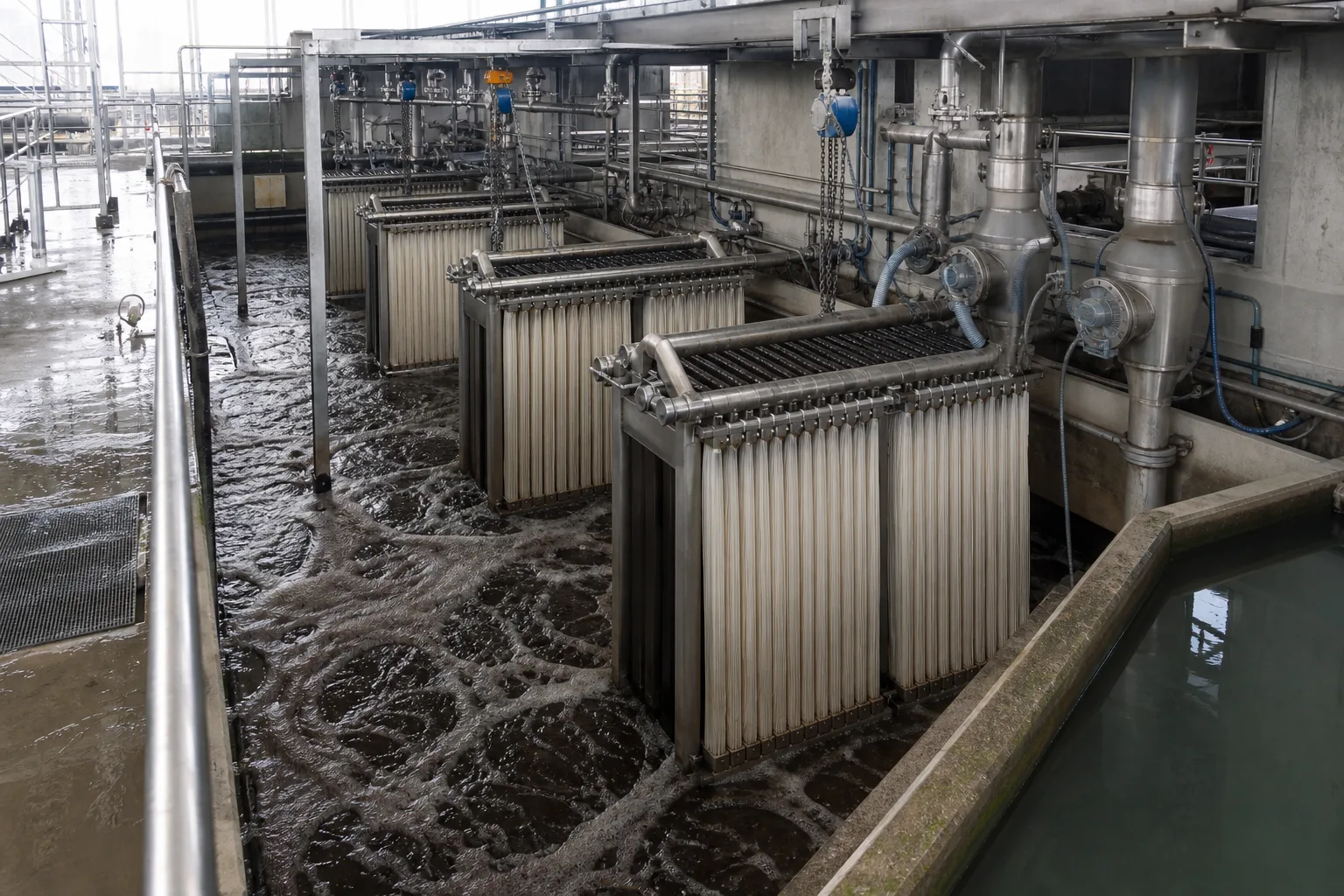 11Submerged membrane cassettes22Activated-sludge mixed liquor33Filtrate collection header44Scour-air and lifting zone
What to identify
- 1Submerged membrane cassettes
- 2Activated-sludge mixed liquor
- 3Filtrate collection header
- 4Scour-air and lifting zone
Key takeaway
An MBR does not feed sludge through a pressurized housing. Membranes stay in biological mixed liquor, suction produces filtrate, air controls deposition and retained solids remain in the biological system.
How to verify on site
Verify tank level, train valves and filtrate flow, membrane-scour air, sludge return/wasting and safe lifting space for each cassette.
The membrane surface is the final solids barrier
At membrane scale, sludge flocs, bubbles and hollow filtrate passages are visible. In this outside-suction example, mixed liquor is outside the fiber and water enters the lumen under vacuum while larger flocs and particles stay outside.
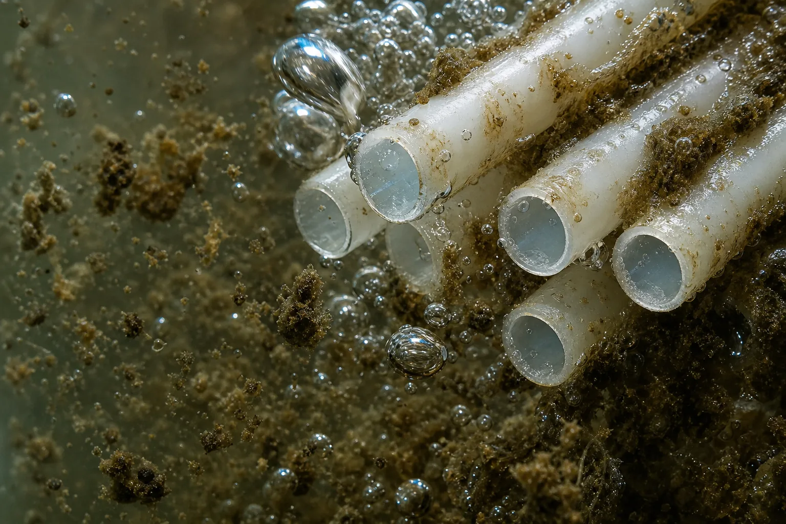 11Activated-sludge floc22Outer membrane surface33Internal filtrate channel44Scouring bubble
What to identify
- 1Activated-sludge floc
- 2Outer membrane surface
- 3Internal filtrate channel
- 4Scouring bubble
Key takeaway
Solids separation comes from intact pores and surface. Dissolved salts and many small molecules can still pass. Their reduction depends mainly on microbial conversion upstream, not direct membrane rejection.
How to verify on site
Sample mixed liquor, supernatant and membrane filtrate together. Compare MLSS/TSS and turbidity with soluble COD or ammonia so biological removal is not confused with membrane retention.
Follow the tank flow to see why sludge stays and water leaves
The cutaway shows a biological mixing zone, bottom aeration, membrane cassettes and a permeate pump. Biology transforms dissolved pollutants before mixed liquor reaches the membrane; filtrate exits while sludge is recycled or wasted.
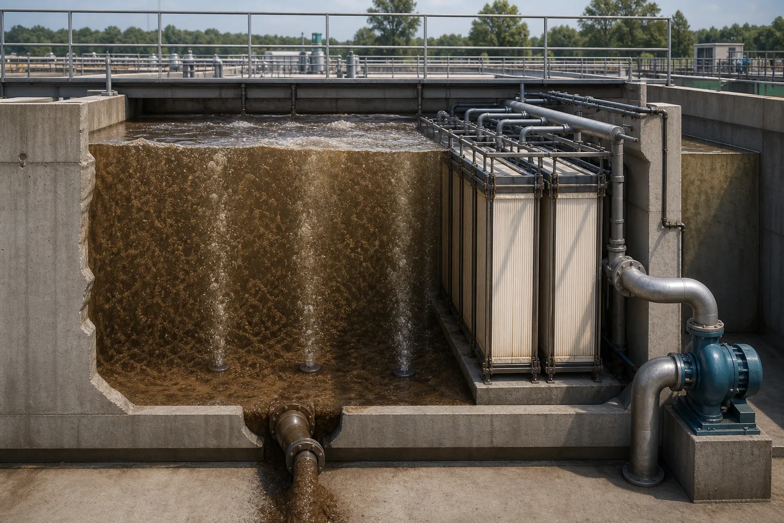 11Biological reaction zone22Under-membrane diffusers33Membrane separation zone44Permeate suction pump
What to identify
- 1Biological reaction zone
- 2Under-membrane diffusers
- 3Membrane separation zone
- 4Permeate suction pump
Key takeaway
MBR partly decouples hydraulic and solids residence times: water can leave through the membrane, while biomass is retained and controlled by return and wasting. This enables high biomass and reliable solids separation together.
How to verify on site
Trace screening, anoxic/aerobic zones, membrane-tank flow, sludge return and wasting. Close both water and solids balances instead of drawing only the permeate line.
Clear filtrate does not mean every operating state is healthy
The pilot tanks show heavy deposits or high solids, a more stable membrane condition, and vigorous or uneven aeration. All three filtrate jars may look clear initially, while TMP, energy and damage risk differ.
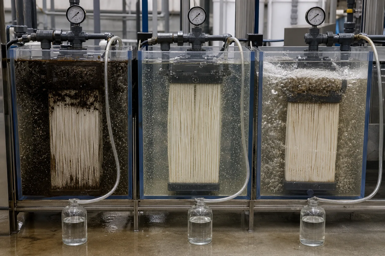 11High load and heavy deposit22Stable filtration state33Strong/uneven aeration44Three filtrate samples
What to identify
- 1High load and heavy deposit
- 2Stable filtration state
- 3Strong/uneven aeration
- 4Three filtrate samples
Key takeaway
The barrier can keep early filtrate clear while fouling or aeration imbalance develops. Health must be judged by TMP/normalized permeability, air distribution, flux and sludge filterability, not one jar.
How to verify on site
Compare train TMP at similar temperature and flux; inspect air distribution, MLSS/viscosity and filterability. Pair them with filtrate turbidity and integrity evidence.
After lifting, distinguish ragging, slime and scale
The removed cassette shows hair and fibrous ragging at left and sticky sludge, biofilm or mineral deposit at right. A clean panel and samples provide reference; different deposits need different causes and responses.
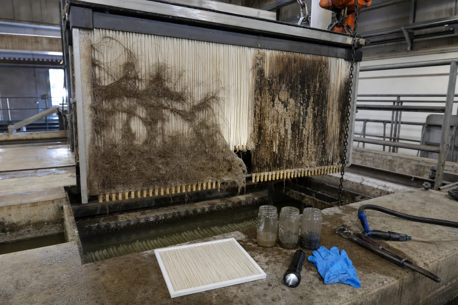 11Hair and fiber ragging22Slime/biofilm deposit33Clean membrane reference44Sludge and cleaning samples
What to identify
- 1Hair and fiber ragging
- 2Slime/biofilm deposit
- 3Clean membrane reference
- 4Sludge and cleaning samples
Key takeaway
Ragging points first to screening, slime to air distribution, flux or sludge condition, and mineral scale to water chemistry. Identify the deposit before mechanical removal, process correction or chemical cleaning.
How to verify on site
Review fine-screen capture and cleaning logs, inspect diffusers by zone and map TMP rise. Use deposit analysis when needed and clean only within membrane-material limits.
Break “sludge stays, water leaves” into five steps
This is the generic causal chain of a submerged MBR. Actual anoxic/aerobic zones, recycle ratios, membrane type and cycles belong to the project design and product manual.
1 Pretreat the influent
Wastewater → fine screen/equalization → biology
Remove hair, plastics and large debris, smooth the load and protect membranes and diffusers.
2 Biological conversion
Dissolved pollutants → metabolism and cell material
Reduce biodegradable COD and, with suitable zones, carry out nitrification, denitrification or biological phosphorus removal.
3 Send mixed liquor to membranes
Activated-sludge mixed liquor → outside the module
Distribute biomass evenly while maintaining liquid level, oxygen and mixing.
4 Draw filtrate
Mixed liquor → pores → filtrate header
Water and permeable small molecules cross; flocs, particles and most microorganisms remain.
5 Return and waste sludge
Retained solids → recycle/waste line
Control MLSS and SRT so viscosity, inert solids and non-biodegradable matter do not accumulate without limit.
What biology, membranes and operation each do
Separate the responsibilities to explain failures correctly. MBR effluent quality is the sum of biological reaction and a physical barrier, not membrane removal alone.
Biological reaction
- Main responsibility
- Biodegrade soluble COD, convert ammonia and produce manageable biomass
- Cannot replace
- Cannot guarantee solids-free effluent; toxic shock and low DO suppress treatment
- Key evidence
- Soluble COD, ammonia/nitrate, DO, ORP, SRT and loading
Membrane solids separation
- Main responsibility
- Retain flocs, suspended solids and most microorganisms; stabilize turbidity
- Cannot replace
- Cannot remove most dissolved salts or freely permeating small molecules
- Key evidence
- Filtrate turbidity/TSS, particles, TMP, flux, permeability and integrity
Aeration and membrane operation
- Main responsibility
- Supply biological oxygen, mix the tank and scour deposits from the membrane
- Cannot replace
- More air is not always better; excessive air wastes energy and may damage modules
- Key evidence
- DO, scour-air flow/pressure, bubble distribution and energy per filtrate volume
Recycle and sludge wasting
- Main responsibility
- Control MLSS, SRT, viscosity and the solids inventory
- Cannot replace
- Membrane retention does not cancel wasting; inert matter still accumulates
- Key evidence
- MLSS/MLVSS, viscosity, waste rate, filterability and solids balance
An MBR membrane is not automatically the final disinfection or reuse barrier. Additional disinfection, carbon, RO or other polishing depends on target contaminants, use and local rules.
Stable operation needs three evidence groups
Flux, TMP and permeability
At comparable temperature, track the TMP needed for equal flux and normalized permeability. A sharp TMP rise can point to air distribution, excessive flux, MLSS or deteriorating sludge.
Air flow, distribution and energy
Scour air must reach every train. Too little promotes deposition; too much wastes energy and may damage elements. Check total flow and visible distribution together.
MLSS, viscosity and biology
Higher MLSS is not always better. Viscosity, DO, F/M, pH, temperature and SRT jointly control mass transfer, filterability and fouling rate.
Route four common signals this way
- Observed signal
- TMP rises while filtrate turbidity stays low
- First suspect
- Surface fouling, uneven scour, excessive flux or poor sludge filterability
- Response order
- Correct air/flux/sludge conditions first, then maintain or chemically clean for the identified deposit
- Observed signal
- Filtrate is clear but COD or ammonia rises
- First suspect
- Biological upset, shock load, low DO, insufficient SRT or toxicity
- Response order
- Check biological influent/effluent, DO/ORP, loading and sludge activity; do not respond with membrane cleaning alone
- Observed signal
- Filtrate turbidity or particles jump suddenly
- First suspect
- Membrane damage, leaking filtrate connection, valve bypass or sampling error
- Response order
- Isolate the train and test integrity and piping; repair and retest rather than increasing aeration
- Observed signal
- Local ragging, thick sludge or large train differences
- First suspect
- Screening failure, uneven feed/air, recycle short circuit or a dead zone
- Response order
- Investigate pretreatment, diffusers and hydraulics; lift and mechanically clean where necessary, then correct the root cause
Three common misconceptions
The membrane directly removes COD, nitrogen and phosphorus
It primarily retains solids and biomass. Most dissolved-pollutant removal needs biological or chemical processes and sometimes downstream polishing.
A membrane retains sludge, so wasting is unnecessary
Cell growth, inert solids and minerals keep accumulating. Sludge wasting controls MLSS, SRT and the solids inventory.
More MLSS and air always stabilize filtrate
Excess MLSS raises viscosity and mass-transfer resistance; excess scour air raises energy and can damage modules. Optimize for the module and sludge state.