Illustrated series · Membranes and separation
How does electrodialysis drive ions in a chosen direction?
Electrodialysis alternates cation- and anion-exchange membranes between two electrodes. DC moves cations toward the cathode and anions toward the anode; each membrane passes only the matching counter-ion, creating alternating dilute and concentrate channels.
Direct answer
Direct answer
Ions move directionally because the electric field supplies direction and fixed-charge membranes supply selectivity. Cations move toward the cathode and cross only cation-exchange membranes; anions move toward the anode and cross only anion-exchange membranes. With CEM and AEM sheets alternating, ions leave one channel on both sides, making it a dilute cell, while the adjacent channel receives them and the next opposite membrane blocks further travel, making it a concentrate cell. Water mainly advances along the channels; ions cross the membranes, and continuous dilute/concentrate flow turns migration into separation.
Directional separation needs four things at once
Electrodes alone do not make ED, and selective membranes do not separate salt without a field and the right stack sequence.
DC defines migration direction
Cations move toward the cathode and anions toward the anode. Reversing polarity reverses migration, which is the basis of periodic EDR reversal.
Fixed charge defines selectivity
A CEM carries fixed negative groups that reject anions and pass cations; an AEM carries fixed positive groups and does the opposite.
Alternating membranes create D and C cells
With CEM and AEM alternating, both ion classes leave a dilute cell but are blocked and accumulated in the neighboring concentrate cells.
Two flowing streams remove the result
Dilute flow carries desalted water and concentrate flow removes accumulated ions. Flow, pressure, current density, and salinity must remain matched.
Start with the plant: stack, power, and separate loops must all exist
The plate-and-frame ED stack connects to DC through red and black cables. Pumps, tanks, and headers sustain dilute, concentrate, and electrode-rinse circuits.
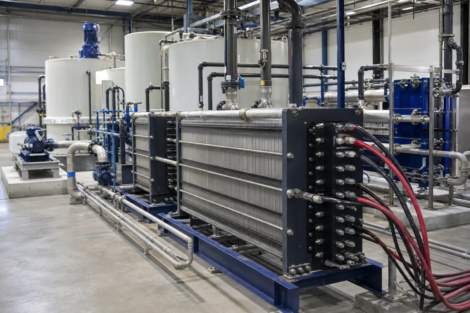 11Electrodialysis stack22Red/black DC cables33Dilute/concentrate tanks44Circulation pumps and headers
What to identify
- 1Electrodialysis stack
- 2Red/black DC cables
- 3Dilute/concentrate tanks
- 4Circulation pumps and headers
What the image proves
ED is not one membrane filtering alone. A stack of selective membranes works with an electric field and paired hydraulic circuits: power transports ions, while water circuits remove the separated streams.
How to verify on site
Trace dilute, concentrate, and electrode-rinse piping for cross-connections. Check polarity, voltage/current, loop flow/pressure, and inlet/outlet conductivity.
Fixed-charge membranes act like two charge-specific gates
The enlarged alternating sheets contain saline channels. Cations move toward the cathode through a CEM; anions move toward the anode through an AEM; fixed charge rejects the co-ion.
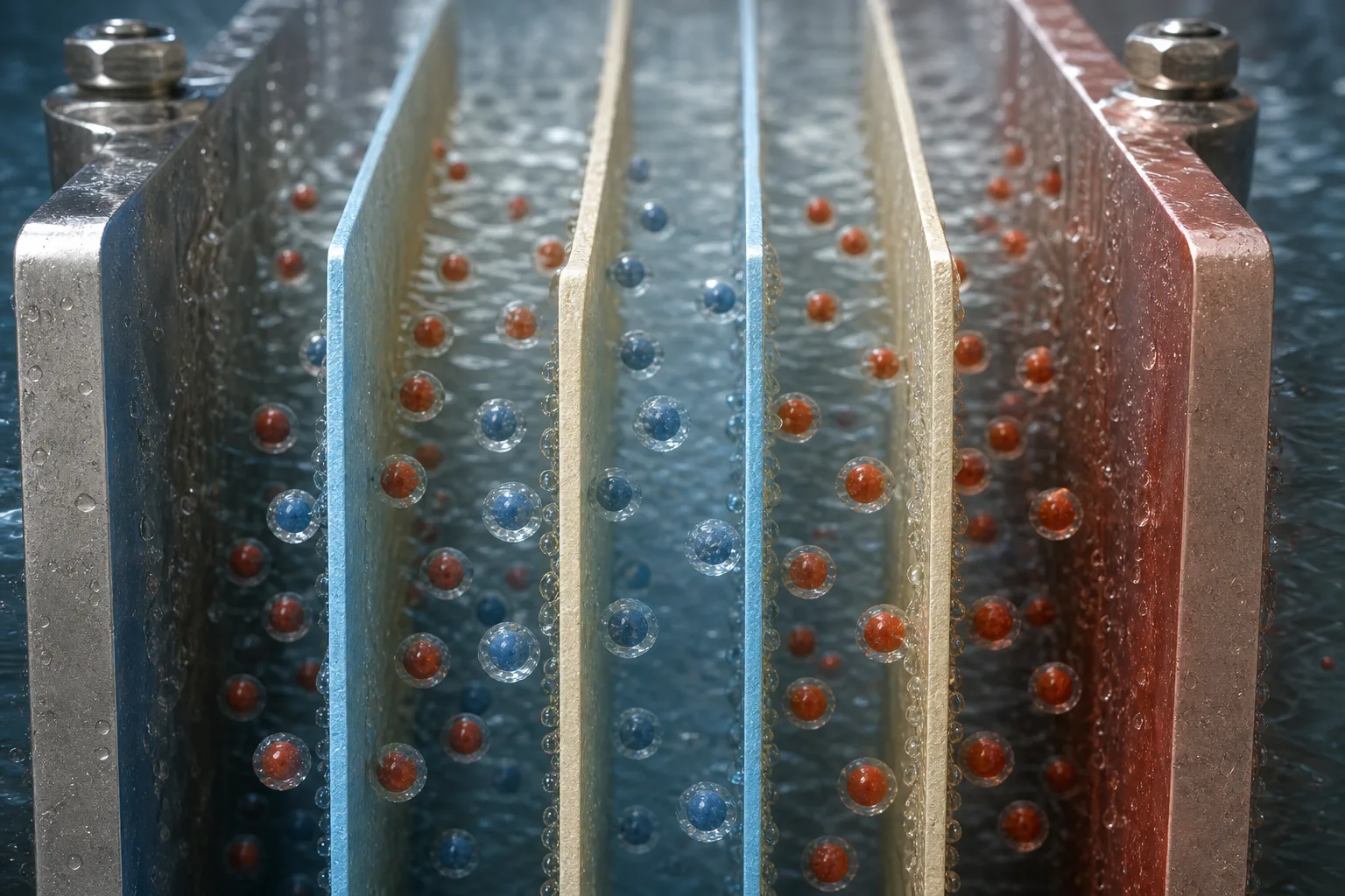 11Cation-exchange membrane CEM22Anion-exchange membrane AEM33Cations moving to cathode44Anions moving to anode
What to identify
- 1Cation-exchange membrane CEM
- 2Anion-exchange membrane AEM
- 3Cations moving to cathode
- 4Anions moving to anode
What the image proves
Selection is electrostatic ion permselectivity, not particle-size sieving; direction comes from the applied DC field. Both are required for charge-specific transfer.
How to verify on site
Verify membrane sequence, face orientation, and polarity against the assembly drawing. A reversed or missing sheet or reversed electrodes can swap expected dilute/concentrate behavior.
Alternating compartments make one stream dilute and the next concentrated
The transparent stack shows clearer low-conductivity channels and darker ion-rich channels. Multiple end ports collect dilute, concentrate, and electrode streams separately.
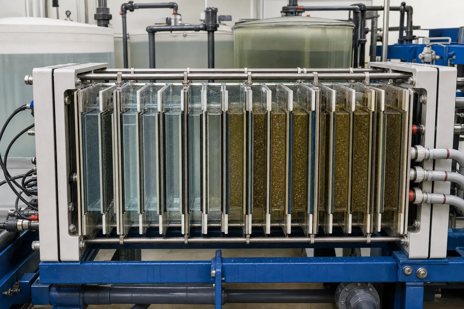 11Low-conductivity dilute cell22High-conductivity concentrate cell33Alternating sheets and spacers44Separated inlet/outlet ports
What to identify
- 1Low-conductivity dilute cell
- 2High-conductivity concentrate cell
- 3Alternating sheets and spacers
- 4Separated inlet/outlet ports
What the image proves
Ions do not disappear inside a membrane; they transfer from dilute to concentrate. Conductivity should fall in one stream and rise in the other so the salt balance can close.
How to verify on site
Measure dilute and concentrate inlet/outlet flow and conductivity together. If dilute salt falls without a matching concentrate gain, check sampling, leakage, deposition, or bypass.
Under-current, matched current, and overlimiting operation look different
Three pilot stacks represent insufficient transport, stable separation, and gas/deposit formation with degraded water. Meters show why voltage, current, and both stream conductivities must be read together.
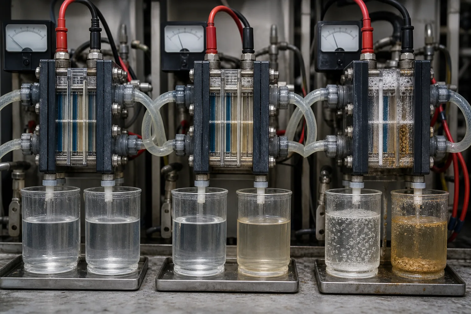 11Under-current/low removal22Current matched to salt load33Overlimiting current/scale and gas44Voltage/current indicators
What to identify
- 1Under-current/low removal
- 2Current matched to salt load
- 3Overlimiting current/scale and gas
- 4Voltage/current indicators
What the image proves
More current initially accelerates transport, but near or above limiting current concentration polarization intensifies. Water splitting, pH shifts, gas, and scale can rise while extra power no longer yields proportional salt removal.
How to verify on site
Establish allowable current density by testing or vendor design. Trend voltage, current, temperature, dilute/concentrate conductivity, pH, and pressure drop instead of turning up the supply blindly.
At teardown, map scale, fouling, membrane damage, and sealing faults
The opened stack shows pale mineral scale, dark organic or metal fouling, a torn membrane, spacers/gaskets, and branch samples. Deposit location is often more diagnostic than color alone.
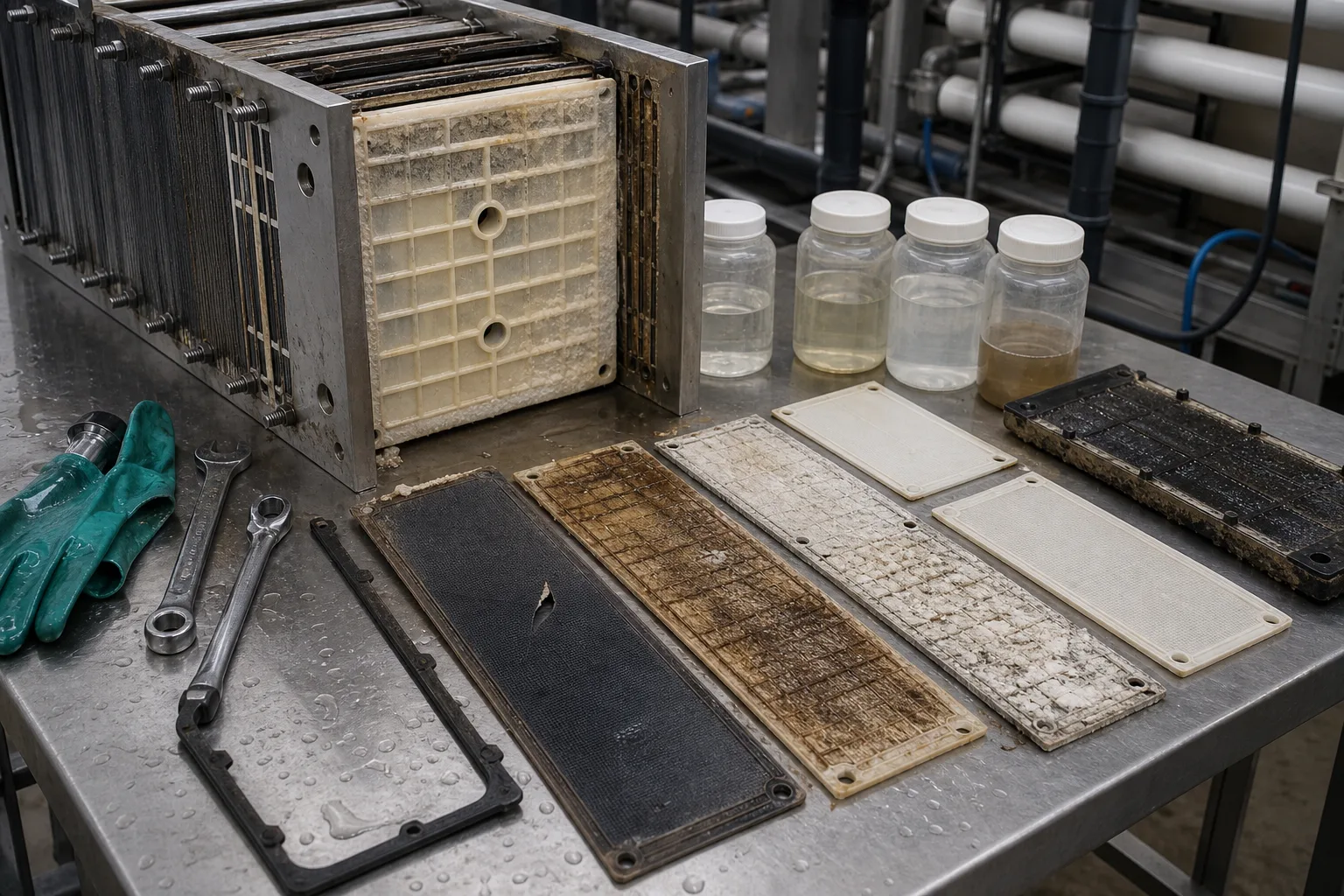 11Pale mineral scale22Dark organic/metal fouling33Torn membrane and spacer44Gasket and branch samples
What to identify
- 1Pale mineral scale
- 2Dark organic/metal fouling
- 3Torn membrane and spacer
- 4Gasket and branch samples
What the image proves
Some mineral scales favor concentrate or cathode-side conditions; organics may foul AEMs and metals/particles can plug spacers. Torn sheets or seal cross-leakage directly remix dilute and concentrate.
How to verify on site
Save branch conductivity, pressure-drop, and polarity history before safe isolation. Mark each sheet position and face, sample deposits and streams, then choose cleaning or replacement.
How do one Na⁺ and one Cl⁻ leave a dilute cell?
A monovalent salt makes direction easiest to see. Multivalent ions, weak electrolytes, co-ion leakage, and water transport modify real selectivity and limiting current.
1 Enter dilute cell
Saline feed → CEM | dilute | AEM
Water advances through the spacer channel with Na⁺ and Cl⁻ in solution.
2 Cation responds
Na⁺ → cathode
Na⁺ moves toward the cathode-side boundary and reaches a CEM.
3 Anion responds
Cl⁻ → anode
Cl⁻ moves toward the anode-side boundary and reaches an AEM.
4 Selective crossing
Na⁺ through CEM; Cl⁻ through AEM
Fixed charge rejects co-ions and preferentially carries counter-ions.
5 Blocked in neighbor
Ion → concentrate → opposite next membrane
The next membrane blocks continued travel, so ions accumulate in concentrate.
6 Two outlets
Dilute → desalted; concentrate → brine
Continuous discharge converts ion transfer into net separation.
Do not confuse ED, EDR, EDI, and bipolar-membrane ED
All use electricity and ion-exchange membranes, but stack structure, operating action, and purpose differ.
ED
- Structure or action
- Alternating CEM/AEM, usually fixed polarity, continuous dilute and concentrate flow
- Primary purpose
- Desalination, concentration, refining, or ion recovery; not automatically final ultrapure water
- Do not ignore
- Both conductivities, salt balance, current efficiency, recovery
EDR
- Structure or action
- Periodically reverses electrode polarity and synchronizes product/concentrate valves
- Primary purpose
- Reversal limits some scale/fouling but cannot replace pretreatment or water-chemistry control
- Do not ignore
- Reversal interval, valve state, transition dump, polarity, conductivity
EDI
- Structure or action
- Resin-filled dilute cells sustain transport and electrical regeneration in low-salt feed
- Primary purpose
- RO-permeate polishing with stricter salt and scaling boundaries than ordinary ED
- Do not ignore
- Product resistivity, feed FCE/CO₂, resin condition, current
BPED
- Structure or action
- Adds bipolar membranes that split water into H⁺ and OH⁻ and combine them with salt ions
- Primary purpose
- Makes acids/bases or changes pH; not an automatic feature of conventional ED
- Do not ignore
- Acid/base concentration, Faradaic efficiency, leakage, mass balance
ED mainly moves charged species. Most neutral organics, particles, and microorganisms are not reliably removed merely because they lack charge; osmosis, electro-osmosis, back diffusion, and co-ion leakage also affect real selectivity.
Stable separation needs three evidence sets
Voltage, current, and limiting-current margin
Resistance and allowable current density change with salinity and temperature. Monitor voltage per cell pair, current efficiency, and polarization rather than treating current as the only control.
Dilute/concentrate flow and salt balance
Record both flows, conductivities, temperature, and recovery together. Salt removed from dilute should appear in concentrate; imbalance exposes leakage, sampling error, deposition, or bypass.
Pressure drop, pH, and branch consistency
Rising drop suggests plugged spacers or deposits; pH shift and gas suggest overlimiting/electrode issues; branch conductivity differences locate cross-leaks, sheets, or valves.
Route four common signals this way
- Signal
- Dilute conductivity removal weakens with normal pressure drop
- First suspects
- Low current, wrong polarity/sequence, high flow, higher feed salinity, or meter error
- Response order
- Retest conductivity/polarity, verify membrane order, flow, temperature, and design current before adjustment
- Signal
- Voltage rises steadily at the same current
- First suspects
- Lower salinity/temperature or extra resistance from scale, fouling, dry zones, or poor contact
- Response order
- Correct for water conditions, then inspect pressure drop, branches, electrodes, and membranes; do not chase current only by voltage
- Signal
- Concentrate turns cloudy, pH jumps, or gas increases
- First suspects
- Near/over limiting current, stronger water splitting, local supersaturation, or electrode-rinse fault
- Response order
- Reduce load and verify flow; measure both pH/conductivity and inspect scale, electrode rinse, and venting
- Signal
- One dilute and concentrate branch suddenly converge in conductivity
- First suspects
- Torn sheet, seal cross-leak, wrong valve state, or failed EDR synchronization
- Response order
- Isolate the branch, verify valves and reversal logic, then pressure/trace-test sheets and seals
Four common misconceptions
ED pushes water through a membrane with pressure
Charged ions are the main species crossing under electrical potential. Water flows along channels, with only secondary osmotic/electro-osmotic transport.
A cation membrane is positively charged
A CEM has fixed negative charge that rejects anions and carries cations. An AEM has fixed positive charge and does the opposite.
More current is always faster and better
Above membrane-surface mass-transfer supply, polarization and overlimiting effects can waste power and amplify pH, gas, and scaling.
Polarity reversal solves all scaling
EDR changes the scaling side and releases some deposits, but correct pretreatment, recovery, flow, and cleaning remain necessary.