Illustrated guides · Physicochemical treatment
What do PAC and PAM each do during coagulation?
PAC usually destabilizes colloids and creates primary microfloc. PAM then bridges those particles into larger, stronger flocs. Their chemistry, preparation, feed points and overdose failure modes are different.
Direct answer
Direct answer
Polyaluminum chloride (PAC) is an aluminum-based inorganic polymeric coagulant. Its hydrolyzed aluminum species and aluminum hydroxide precipitates neutralize charge, adsorb material and sweep-enmesh colloids, producing destabilized primary floc. Polyacrylamide (PAM) is a high-molecular-weight polymer commonly used as a flocculant or coagulant aid. Long chains adsorb at multiple particle surfaces and bridge microflocs into larger, stronger aggregates. A typical arrangement disperses PAC at rapid mix, allows initial destabilization, then feeds properly dissolved and aged PAM under gentler mixing before staged flocculation. This is not a universal recipe: PAM charge, molecular weight and hydrolysis must match the water, and some cationic polymers can act as primary coagulants. Jar or pilot testing must optimize final clarification, flotation, filtration, sludge and residual performance rather than floc appearance alone.
Four boundaries make PAC and PAM work as a sequence
Two running pumps do not prove that the chemistry, solution preparation and hydraulic timing are correct.
PAC first destabilizes the full flow
Fast hydrolysis and surface reactions require suitable pH/alkalinity and effective rapid mixing. Local concentration produces local excess and untreated zones.
PAM chemistry matches the solids
Anionic, cationic and nonionic products, molecular weight and hydrolysis affect adsorption and chain extension. Products are not interchangeable by dose.
PAM is wetted, dissolved and aged
Poor wetting produces fisheyes, high concentration resists dispersion, insufficient aging leaves chains undeveloped, and severe shear can damage them.
Feed interval and shear are compatible
Too-early PAM can be trapped or compete in concentrated chemistry; too-late addition misses collisions. Downstream mixing must disperse polymer without repeatedly breaking floc.
Liquid PAC feed and dry-PAM make-down are normally separate systems
The large tank represents PAC storage and the metering line feeds rapid mix. The hopper, wetting equipment and preparation tank convert dry PAM into an aged working solution.
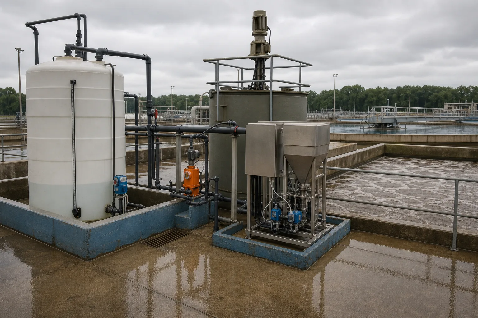 11PAC storage and level22PAC metering/injection line33PAM dissolution and aging44Dry-PAM hopper and feeder
What to identify
- 1PAC storage and level
- 2PAC metering/injection line
- 3PAM dissolution and aging
- 4Dry-PAM hopper and feeder
What the image proves
PAC is continuously metered as product or active aluminum mass. PAM must first be fed, wetted, dissolved and aged before low-concentration dosing. Direct powder addition or prolonged concentrated storage causes fisheyes, plugging and variable active dose.
How to verify on site
Verify PAC strength/basicity, tank level, pump calibration and injection valve; verify PAM grade/batch, powder feed, make-up water, solution strength, aging time, agitation and tank changeover.
PAC creates bridgeable microfloc; PAM chains connect it
Mineral cores represent colloids, pale deposits PAC hydrolysis products and transparent chains PAM bridges. This is a mechanism visualization, not a literal product micrograph.
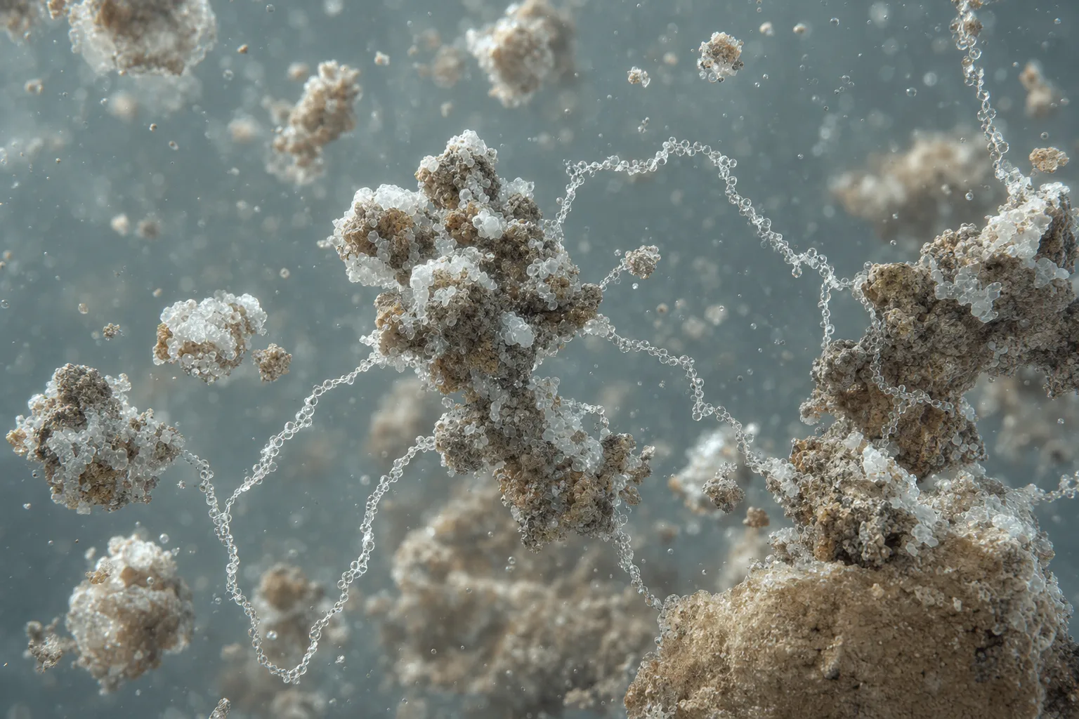 11Original colloid core22PAC hydrolysis/primary floc33Long PAM chain44Multipoint adsorption bridge
What to identify
- 1Original colloid core
- 2PAC hydrolysis/primary floc
- 3Long PAM chain
- 4Multipoint adsorption bridge
What the image proves
PAC changes charge and surface condition before PAM bridging. PAM should retain free chain segments that attach elsewhere; excess can coat separate particles, reduce interparticle bridges and restabilize the suspension.
How to verify on site
Compare PAC-only, PAM-only and combined jar tests. Use charge/streaming-current evidence when available plus microfloc onset, strength, supernatant particles and filtration/dewatering response.
PAC typically enters rapid mix; PAM follows after primary floc forms
The cutaway moves from intense PAC dispersion through microfloc formation, gentler PAM distribution and final floc growth into clarification.
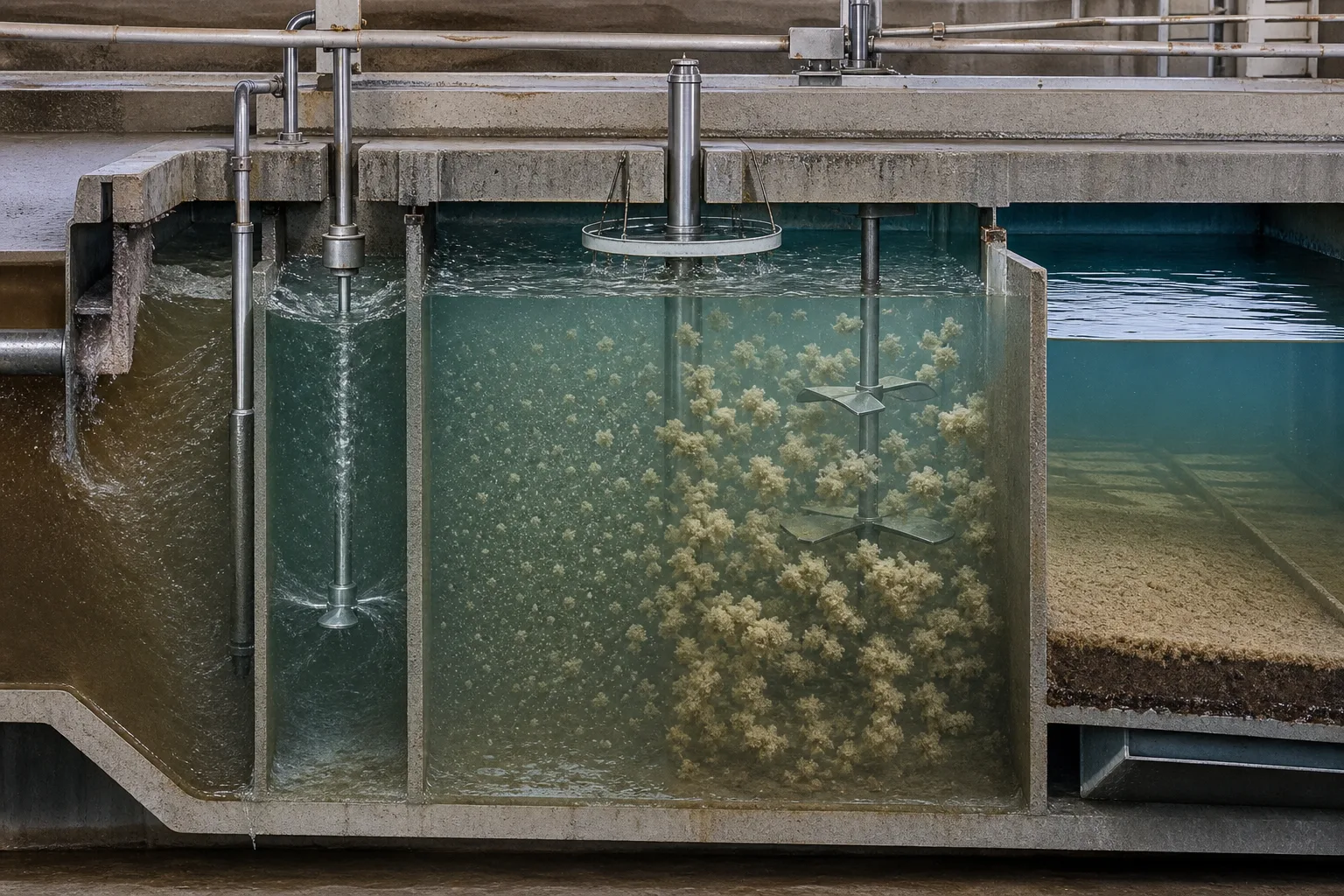 11PAC feed and rapid mix22Primary-microfloc zone33PAM feed/gentle dispersion44Large floc to clarification
What to identify
- 1PAC feed and rapid mix
- 2Primary-microfloc zone
- 3PAM feed/gentle dispersion
- 4Large floc to clarification
What the image proves
Co-feeding at one high-shear point can expose PAM to concentrated chemistry, competitive adsorption and chain shear. Excessive spacing can also allow deposition or breakage. The interval is set by real residence time and mixing energy, not a fixed distance.
How to verify on site
Measure PAC-to-PAM and PAM-to-separator residence times at actual flow; inspect backflow, short circuiting, mixer energy and samples along the path to locate microfloc and large-floc formation.
Jar tests separate weak destabilization, useful bridging and polymer excess
The beakers show dispersed fines, a dense-floc candidate and a loose/stringy or mismatched candidate. The foreground liquid represents polymer working solution.
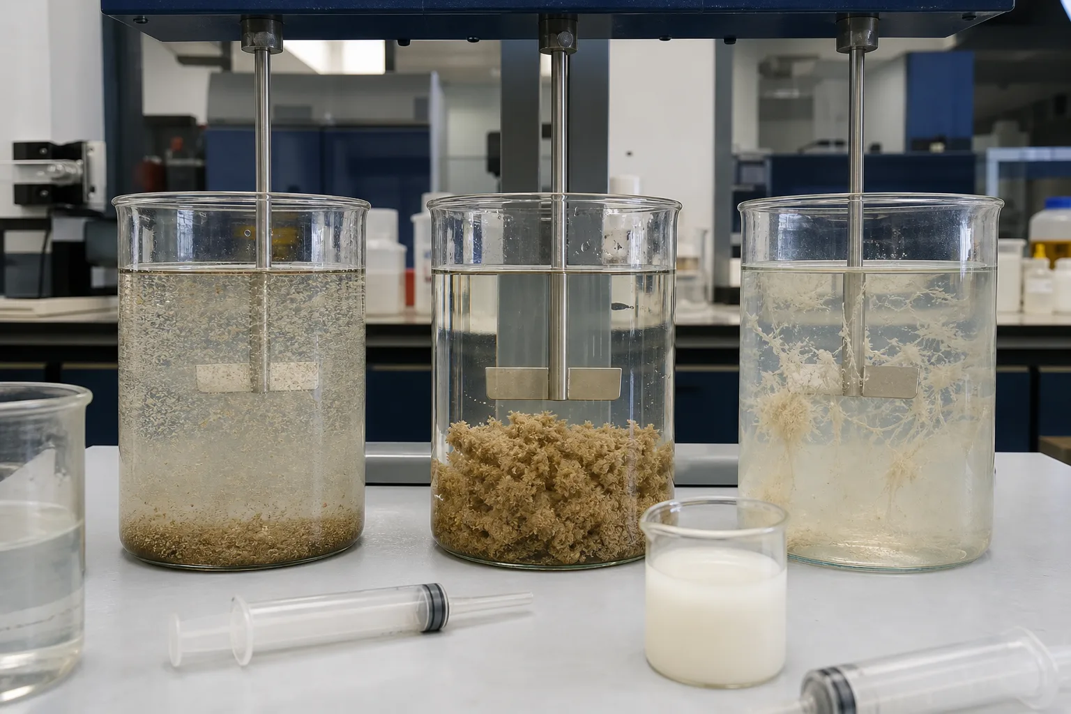 11Low PAC: dispersed fines22Combined working window33PAM excess/mismatch44PAM solution and dose
What to identify
- 1Low PAC: dispersed fines
- 2Combined working window
- 3PAM excess/mismatch
- 4PAM solution and dose
What the image proves
Fast, large floc is not automatically optimum. PAM excess can create loose, sticky or poorly filterable floc; PAC excess can depress pH, increase aluminum residual and sludge. Optimize total treatment and chemical demand.
How to verify on site
After a PAC gradient, test PAM type, dose and addition time around promising PAC points. Hold mixing constant and measure supernatant turbidity/particles, pH, residual aluminum, settling/sludge and filtration or dewatering.
Troubleshooting must connect plugging, solution condition, jars and full-scale hydraulics
A blocked fitting, staged samples, fouled injection hardware and the treatment basin represent delivery, chemical response and full-scale reproduction.
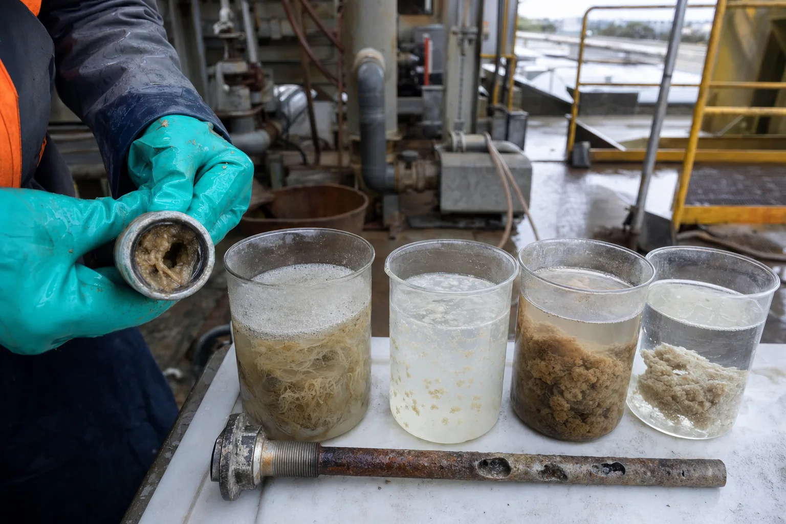 11Blocked head/check valve22Staged floc/supernatant33Scaled injection hardware44Full-scale mixing/separation
What to identify
- 1Blocked head/check valve
- 2Staged floc/supernatant
- 3Scaled injection hardware
- 4Full-scale mixing/separation
What the image proves
‘Chemical on, no effect’ may be delivery rather than formulation: PAC crystallization, PAM fisheyes, low real pump output, changing backpressure, drifting sensors or stopped mixers all separate setpoint from real dose.
How to verify on site
Calibrate both pumps volumetrically under realistic backpressure; inspect valves, diaphragms, quills and make-down screens; sample raw, post-PAC, post-PAM and separated water while recording strength, pH, turbidity and equipment state.
Six steps in the PAC–PAM sequence
Separating solution preparation, destabilization and bridging shows which stage to correct.
1 Stable raw water
Charged colloids + organics
Charge and hydration maintain dispersion.
2 PAC rapid mix
Active Al species → full flow
Neutralize/adsorb uniformly and form hydroxide.
3 Primary floc
Destabilized solids + Al(OH)₃
Create surfaces that PAM can connect.
4 Gentle PAM dispersion
Aged chains → microfloc
Extend chains and adsorb at several surfaces.
5 Bridging and growth
Microfloc → larger/stronger floc
Improve settling, flotation, filtration or dewatering.
6 Separation feedback
Effluent + sludge + residuals
Set the combined chemical-hydraulic window.
Distinct responsibilities of PAC, PAM, mixing and separation
The chemicals are not substitutes, and dosing cannot hide failed equipment.
PAC primary coagulation
- Primary duty
- Change colloid charge/surface rapidly and provide hydroxide sweep solids
- Typical imbalance
- Wrong type/dose, pH/alkalinity, local excess or degraded product
- Field evidence
- Active-Al mass dose, pH/alkalinity, primary floc, aluminum residual and PAC curve
PAM flocculant aid
- Primary duty
- Use matched long chains to bridge and strengthen destabilized particles
- Typical imbalance
- Wrong charge/MW, poor aging, fisheyes, coating excess or chain shear
- Field evidence
- Grade/batch, preparation strength/time, solution quality, floc strength and PAM gradient
Feed and mixing
- Primary duty
- Give PAC fast dispersion and PAM gentle distribution/collision windows
- Typical imbalance
- Co-feed interference, bad interval, short circuit, dead zone or high shear
- Field evidence
- Feed points, residence, power/speed, staged samples and floc-onset location
Separation and sludge
- Primary duty
- Capture floc and return effluent, filter and sludge evidence
- Typical imbalance
- Poor fit to separator; excess chemicals increase sludge or stickiness
- Field evidence
- Turbidity/TSS/particles, settling, filter run, sludge/dewatering and residuals
PAC and PAM are product classes, not single formulations. Active content/basicity, charge, molecular weight and hydrolysis can differ widely. Potable-water use also requires approved products and control of residual monomers/impurities. Re-test every formulation change.
Align three operating evidence groups
Raw water and PAC window
Flow, turbidity/TSS, color or TOC, pH, alkalinity, temperature; PAC strength/batch, active mass dose, pump output and aluminum residual.
PAM make-down and floc profile
Charge/MW, powder feed, water, working strength, aging/storage, feed interval, and floc size/strength after PAC, PAM and final stage.
Separation and cost
Effluent turbidity/TSS/particles, settling or float, filter run/DP, sludge/dewatering, PAC/PAM consumption, residuals and plugging/cleaning events.
Which chemical should be suspected first?
- Combined signal
- No primary floc after PAC; PAM only produces stringy fines
- First suspicion
- PAC destabilization failed because of dose, pH/alkalinity, rapid mix or delivery
- Next action
- Verify PAC mass dose and mixer, then test a PAC×pH matrix before adding more PAM
- Combined signal
- Many primary flocs after PAC remain small/loose after PAM
- First suspicion
- PAM grade/dose, preparation, feed point or gentle mixing is wrong
- Next action
- Inspect fisheyes and solution, then test PAM type×dose×addition time and floc strength
- Combined signal
- PAM makes rapid large but sticky/loose floc, filter worsens or fines return
- First suspicion
- PAM excess, surface coating, wrong charge or downstream shear
- Next action
- Step PAM down at constant PAC, inspect downstream shear and judge filtration/dewatering, not appearance
- Combined signal
- Jars are stable but plant performance cycles or parallel trains differ
- First suspicion
- Strength/aging, pump calibration, backpressure, flow split, mixer or sensor
- Next action
- Mass-balance each train, volumetrically calibrate pumps and collect simultaneous staged samples
Four common misconceptions
PAM is simply a stronger coagulant
The usual sequence is PAC destabilization then PAM bridging. Some cationic polymers can coagulate, but that is a separately tested case.
Co-feeding PAC and PAM saves equipment
One high-shear point raises risks of local interference and chain damage; sequence and interval must be tested.
More viscous PAM and larger floc are better
Viscosity is not bridging performance; overdose can coat solids and create loose, sticky, poorly filterable floc.
Same pump percent means same dose
Strength, aging, calibration, backpressure, valves and real water flow determine active mass per cubic metre.