Illustrated series · Membranes & separation
What is the difference between UF, NF and RO?
All three use pressure to move water across a membrane, but their structures, separation mechanisms, target contaminants, pressure requirements and residual streams are different. The five visuals compare the equipment, membrane interface, flow path, product-water goal and diagnostic evidence.
The short answer
The short answer
UF primarily uses defined pores to screen particles, colloids and microorganisms. NF combines size and charge effects and is often selected for softening, multivalent ions and some organics. RO uses a denser selective layer and enough pressure to overcome osmotic pressure, removing most dissolved salts. Selection starts with the removal target, then product quality, energy and concentrate limits.
Answer four questions before selecting a membrane
Systems can look similar from the outside. Define these four boundaries before choosing a membrane family or model.
What must be removed?
Use UF for particles, colloids and microorganisms; consider NF for hardness, color and larger organics; use RO when dissolved salts and monovalent ions must be strongly reduced.
What product quality is required?
Clarification, softening and desalination are different jobs. A rejection percentage is meaningful only against a defined product-water target.
Can the pressure and energy be supported?
Required driving force generally rises from UF to NF and RO. RO must also overcome feed osmotic pressure, which increases with salinity.
Where will the residual stream go?
UF generates backwash waste; NF and RO continuously produce concentrate. Flow, salt load and final disposal belong in the initial design.
Start with the three systems: modules and pressure shape the equipment
The left skid uses vertical hollow-fiber UF modules. The center and right use pressure vessels and pumps typical of spiral-wound NF/RO systems. Appearance is a clue, not proof of membrane type.
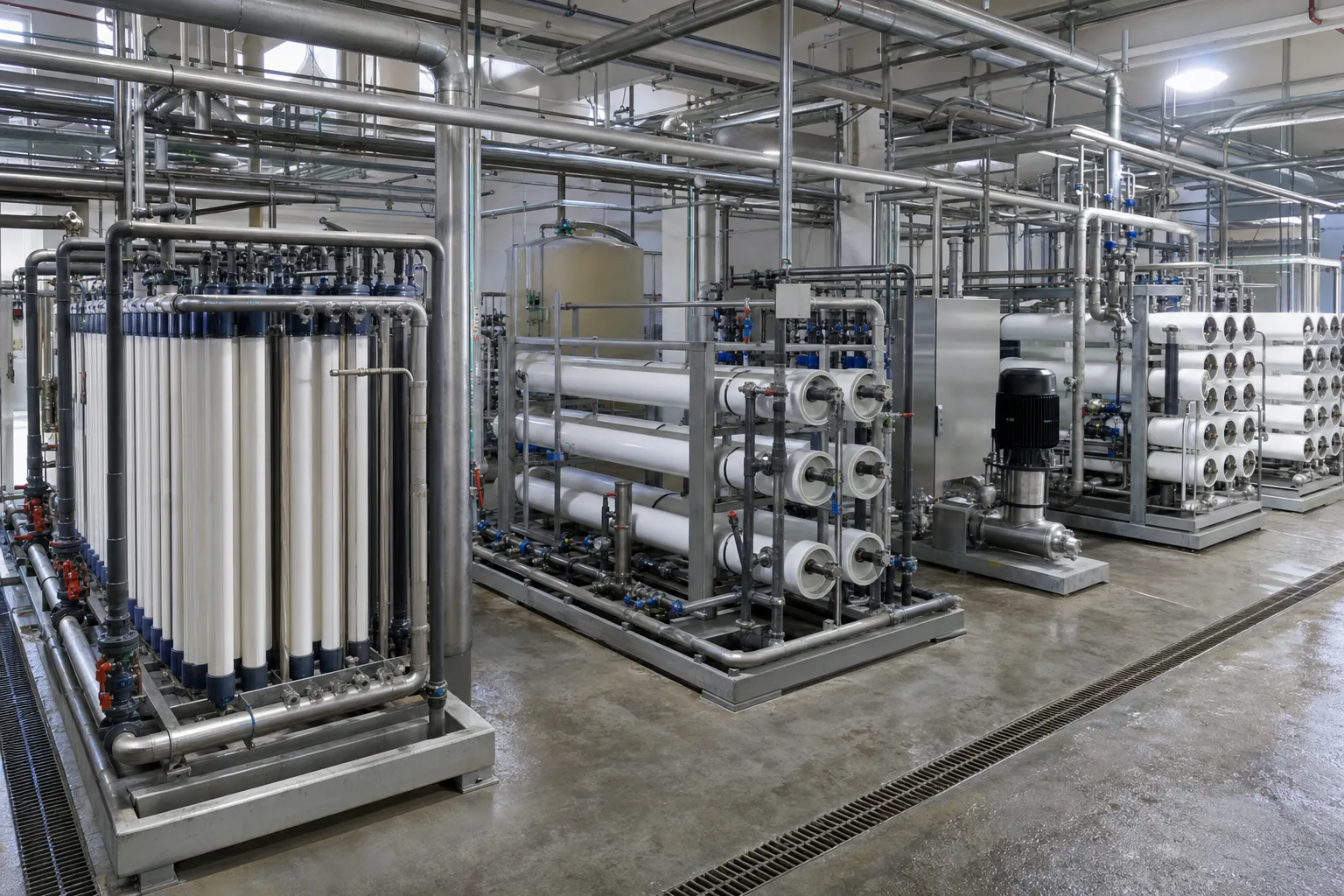 11Hollow-fiber UF22Spiral-wound NF33High-pressure pump44RO pressure vessels
What to identify
- 1Hollow-fiber UF
- 2Spiral-wound NF
- 3High-pressure pump
- 4RO pressure vessels
Key takeaway
UF often serves as a lower-pressure particle barrier. NF and RO commonly use spiral-wound elements at higher pressure; the decisive differences are in the selective layer, target solutes and operating data.
How to verify it on site
Read the element model, design pressure, feed/permeate conductivity and concentrate piping. NF and RO are easy to confuse from a skid photo alone.
The difference is not simply an ever-smaller pore
UF can be understood through pore sieving. NF is influenced by both size and membrane charge. A dense RO polymer layer is better described by differences in water and solute sorption and diffusion.
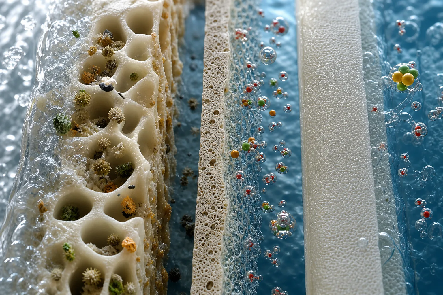 11UF: pore sieving22NF: size effect33NF: charge effect44RO: dense layer
What to identify
- 1UF: pore sieving
- 2NF: size effect
- 3NF: charge effect
- 4RO: dense layer
Key takeaway
The 'smaller pore' idea is only a first mental model. In NF and RO, membrane chemistry, solute charge and osmotic pressure materially change performance.
How to verify it on site
Do not replace product data with one alleged pore-size number. Check target-solute rejection, test conditions, feed composition, temperature and recovery.
Module construction controls how water meets the membrane
UF often packs many hollow fibers in parallel. NF and RO commonly wind membrane sheets, feed spacers, permeate carriers and a central tube into one element. Construction determines flow, cleaning and failure evidence.
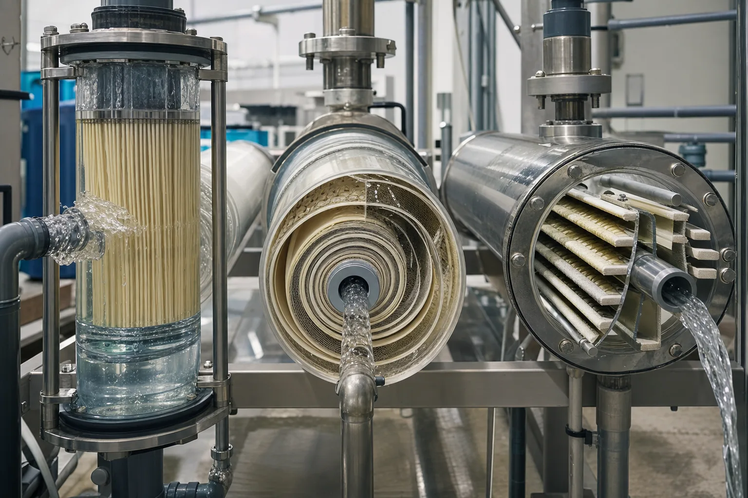 11UF fiber bundle22Spiral membrane leaves33Feed spacer44Permeate tube
What to identify
- 1UF fiber bundle
- 2Spiral membrane leaves
- 3Feed spacer
- 4Permeate tube
Key takeaway
UF integrity centers on fibers and pores. NF/RO integrity centers on membrane leaves, spacers, the product tube and end seals. Similar fouling produces different operational evidence.
How to verify it on site
For UF, follow TMP, backwash recovery and integrity. For NF/RO, follow stage pressure drop, normalized permeate flow, rejection and interconnector or O-ring condition.
The three systems pursue different product-water goals
With the same feed, UF targets clarity and microorganisms; NF targets hardness, color and larger organics; RO further lowers total dissolved salts. Backwash waste and concentrate remain part of the process.
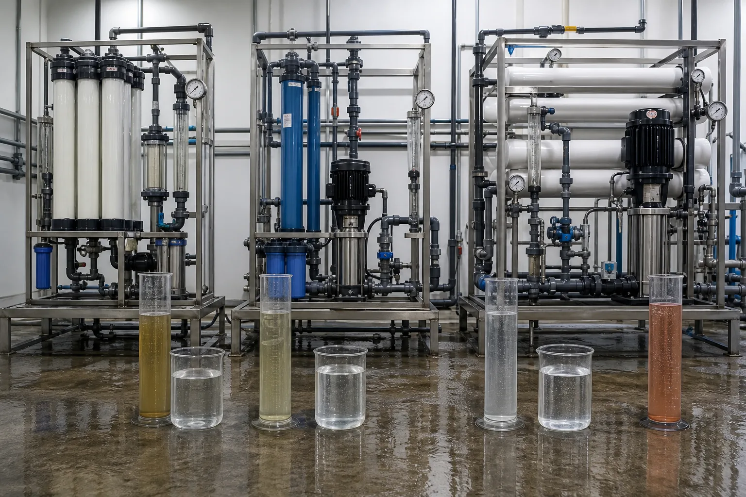 11UF: particle barrier22NF: softening/organics33RO: desalination44Concentrate/waste
What to identify
- 1UF: particle barrier
- 2NF: softening/organics
- 3RO: desalination
- 4Concentrate/waste
Key takeaway
All three permeates may look clear, but clarity is not low salinity. UF permeate may retain high conductivity, NF may pass part of the monovalent salt, and RO is the main desalination barrier.
How to verify it on site
Sample feed, permeate and concentrate together. Compare turbidity, hardness, TOC/UV254 and conductivity/TDS instead of relying on appearance.
Failed modules can look similar, but diagnosis is different
Removed modules may show sludge, organic or biological films, deformed membrane sheets and mineral crystals. Appearance is only evidence when matched to trends, stage position and cleaning response.
 11UF fiber fouling22Organic/biofouling33Sheet deformation44Mineral scale
What to identify
- 1UF fiber fouling
- 2Organic/biofouling
- 3Sheet deformation
- 4Mineral scale
Key takeaway
UF plugging often first appears as rising TMP or falling flux. NF/RO fouling and scale affect pressure drop and normalized flow, while membrane or seal damage more directly reduces rejection.
How to verify it on site
Verify instruments and comparable operating conditions first, then use staged sampling, deposit analysis and targeted cleaning. Do not choose chemicals from a photograph alone.
Put all three membranes in one selection table
This table builds engineering intuition; it does not replace product datasheets or feed-water testing. NF and RO boundaries vary by membrane chemistry and product family.
UF
- Dominant transport view
- Defined pores; mainly sieving
- Main rejection targets
- Suspended solids, colloids, bacteria and larger molecules
- What normally passes
- Dissolved salts and most small molecules
- Pressure intuition
- Lower
- Typical engineering task
- Clarification, particle barrier, RO pretreatment
NF
- Dominant transport view
- Size exclusion plus charge effects
- Main rejection targets
- Hardness, multivalent ions, color and some organics
- What normally passes
- Some monovalent salts and water
- Pressure intuition
- Medium to high
- Typical engineering task
- Softening, color and organic control
RO
- Dominant transport view
- Dense selective layer; solution-diffusion is more useful
- Main rejection targets
- Most dissolved salts, monovalent ions and small contaminants
- What normally passes
- Mainly water, with a small salt passage
- Pressure intuition
- Higher and strongly constrained by osmotic pressure
- Typical engineering task
- Brackish/seawater desalination, process demineralization, reuse
Do not treat NF and RO as screens with one fixed pore-size scale. Membrane chemistry, solute size and charge, concentration polarization and operating conditions all affect rejection.
Three practical selection rules
If the job is only particles, do not start with RO
For turbidity, colloids or a microbial barrier, UF can often meet the target at lower pressure and also protect downstream NF/RO.
Softening does not always require RO
When hardness, multivalent ions, color or larger organics dominate, NF may provide a better balance between product quality and energy.
For desalination, return to RO net driving pressure
Strong TDS and monovalent-salt reduction requires checking RO net driving pressure, salt passage, recovery and concentrate handling—not only nominal rejection.
Three common mistakes
They differ only by pore size
Pore sieving explains UF well, while NF/RO also involve charge, dense selective layers, solution-diffusion and osmotic pressure.
Clear water means desalinated water
UF can make water optically clear without materially removing most dissolved salts. Conductivity, TDS or ion analysis is required.
The tightest membrane is always best
Tighter membranes generally increase pressure, pretreatment and concentrate-management demands. The best membrane is the least intensive one that reliably meets the product goal.