Illustrated guide · Industrial water systems
How does a ZLD system progress from membrane concentration to crystallization?
Follow segregation, membrane recovery, evaporation, controlled supersaturation, solids separation and mother-liquor recycle as one water, salt, heat and solids boundary.
Direct answer
Direct answer
Zero liquid discharge is a system boundary, not a single dryer. Compatible streams are equalized and pretreated first; suitable membrane processes then recover the lower-energy fraction of water until osmotic pressure, scaling, viscosity, membrane pressure or acceptable flux sets the limit. Evaporation removes more water from the membrane concentrate and condenses the vapor as distillate, while demisting, foaming control and volatile-species management protect reuse quality. At saturation, a crystallizer deliberately controls supersaturation with circulation, seed inventory, temperature or vacuum and residence time so salts grow on suspended crystals instead of uncontrolled heat-transfer surfaces. A centrifuge or filter separates wet crystals, mother liquor is managed or recycled, and the solids are characterized for reuse or disposal. ZLD means no routine liquid-waste discharge across the declared boundary; it does not mean zero waste, zero energy, zero water loss or automatically saleable salt. A defensible system closes both the water balance and the dissolved-solids balance, including wet-cake moisture, vents, leaks, cleaning inventories, deposits and any liquid sent off site.
Four boundaries make ZLD sustainable
Each step changes the chemistry and duty of the next; three equipment packages do not form a ZLD system by themselves.
Segregate before deciding what can mix
Hardness, silica, oil, organics, ammonia, volatile and corrosive streams require different controls. A wrong blend can precipitate, foam, foul or react before treatment begins.
Stop membrane recovery at its real limit
Higher recovery raises brine salinity, osmotic pressure, ion activity, viscosity and concentration polarization. Saturation, normalized performance and allowed pressure define the membrane endpoint.
Move precipitation from surfaces to seeds
The evaporator removes water; the crystallizer controls supersaturation. Circulation, seed inventory and slurry withdrawal should favor crystal growth rather than scale on tubes, nozzles and lines.
Declare every water, salt, heat and cleaning outlet
Distillate still needs quality release; wet salt carries liquor and CIP creates brine. Recycle, storage, off-site handling and vent condensate all belong in the claim.
A full ZLD hall places membrane concentration, thermal recovery, dewatering and products inside one boundary
Membrane vessels sit left, the vertical evaporator/crystallizer train is central, and the centrifuge discharges wet crystals at right; recovered water and salt must both be accounted for.
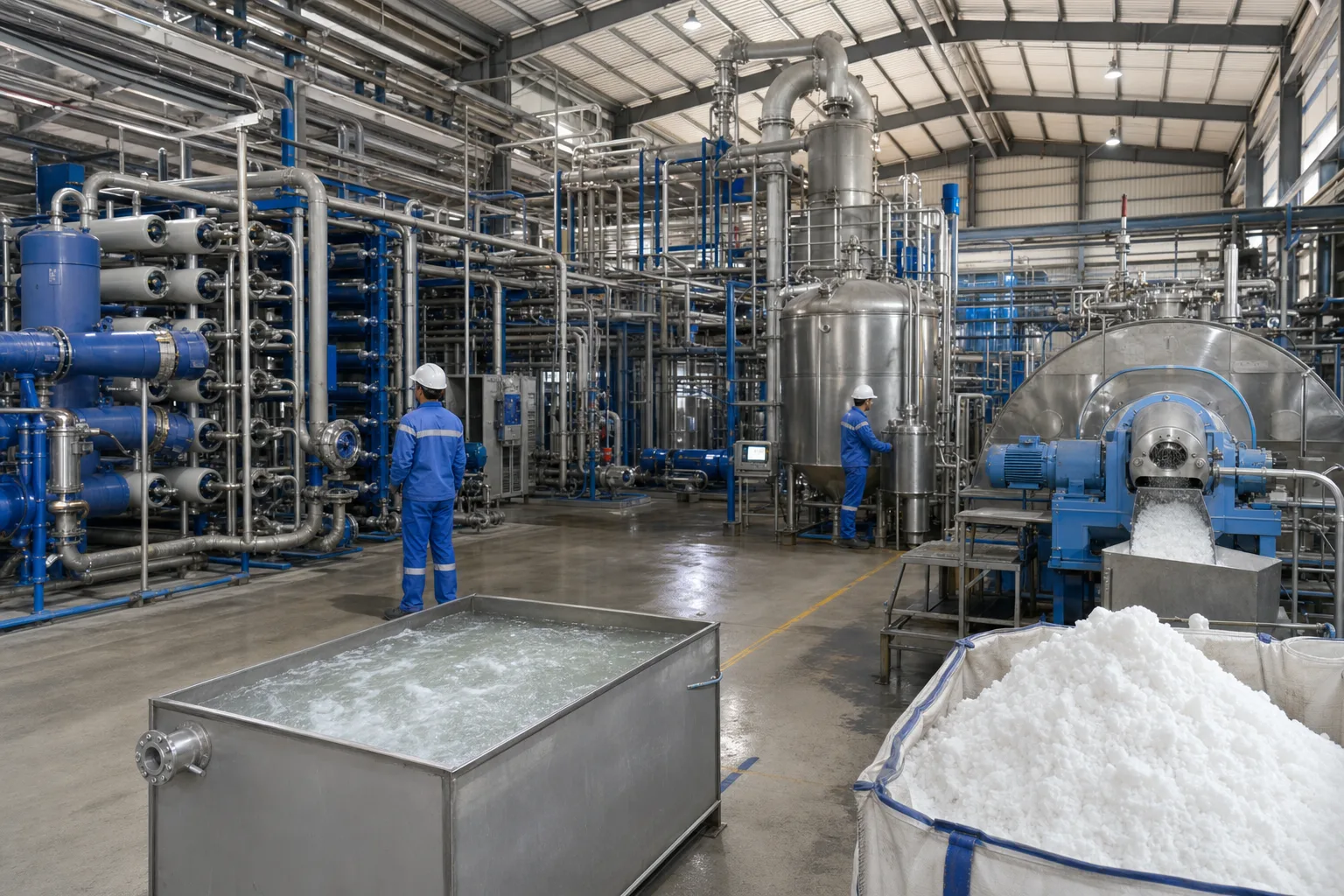 11Membrane vessels and high-pressure piping22Vertical evaporation/crystallization vessels33Centrifuge and slurry paths44Recovered water and wet-salt outputs
What to identify
- 1Membrane vessels and high-pressure piping
- 2Vertical evaporation/crystallization vessels
- 3Centrifuge and slurry paths
- 4Recovered water and wet-salt outputs
What the image proves
Membranes normally recover the easier water before thermal treatment; every extra unit of membrane concentrate becomes evaporation duty.
How to verify it
Close 24-hour flow, TDS/ion, distillate, wet-salt dry-mass and inventory balances across all four areas.
Stage samples and a bench crystallizer reveal where water, salts and residual contaminants go
Bottles represent pretreatment, membrane concentrate, crystal-bearing mother liquor and distillate; the stirred vessel shows suspended crystal growth.
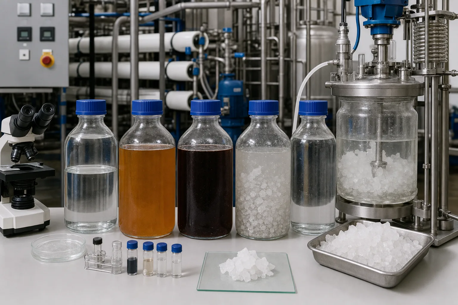 11Feed and pretreated-water samples22Membrane concentrate and accumulated organics33Mother liquor and crystal-size evidence44Condensed distillate quality sample
What to identify
- 1Feed and pretreated-water samples
- 2Membrane concentrate and accumulated organics
- 3Mother liquor and crystal-size evidence
- 4Condensed distillate quality sample
What the image proves
Clear water does not prove salt destruction: each separation moves salts into a smaller liquid or solid stream, while organics and volatiles may behave differently.
How to verify it
Sample both sides of every split and analyze flow, key ions, organics, volatiles, crystal phase, size and entrained mother liquor.
An integrated skid links membrane permeate, evaporation, centrifuge and reuse storage
The membrane rack is left, thermal circulation is central, the horizontal centrifuge is right and the rear tank receives recovered water or buffer liquid.
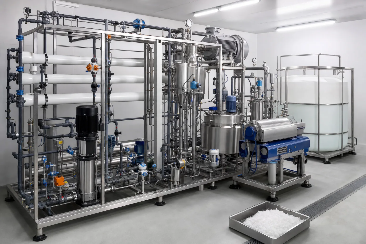 11Membrane permeate/concentrate split22Evaporator circulation and vapor separator33Slurry dewatering centrifuge44Reuse tank and wet-salt tray
What to identify
- 1Membrane permeate/concentrate split
- 2Evaporator circulation and vapor separator
- 3Slurry dewatering centrifuge
- 4Reuse tank and wet-salt tray
What the image proves
Recycle creates inventory: non-crystallizing species can accumulate indefinitely unless the design explicitly controls their endpoint.
How to verify it
Trace permeate, concentrate, distillate, mother liquor, centrate and CIP returns; trend each accumulating species and disclose any purge or off-site liquid.
Three operating states separate clean heat transfer, controlled crystallization and uncontrolled scale
The clean baseline, seeded slurry and heavily encrusted unit show why salt on crystals is productive while salt on equipment destroys capacity.
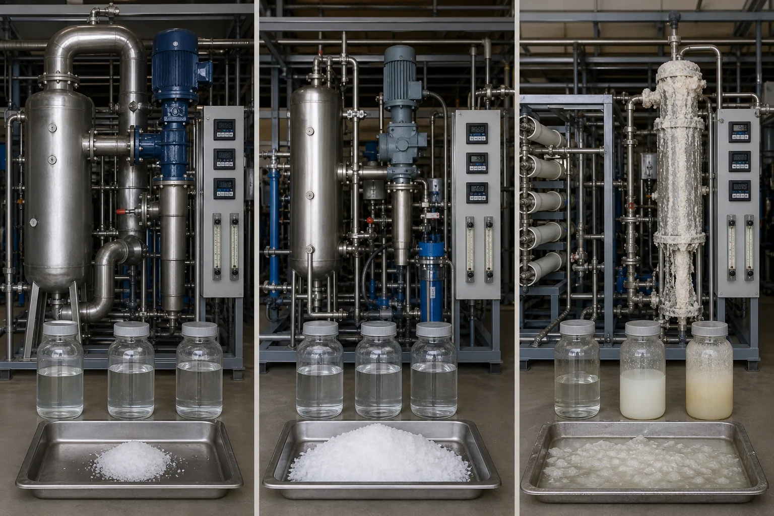 11Clean heat-transfer and circulation baseline22Seeded crystal growth and normal withdrawal33Uncontrolled scaling and plugging44Distillate, liquor and salt balance evidence
What to identify
- 1Clean heat-transfer and circulation baseline
- 2Seeded crystal growth and normal withdrawal
- 3Uncontrolled scaling and plugging
- 4Distillate, liquor and salt balance evidence
What the image proves
High salt production is not the same as high scaling; controlled supersaturation consumes driving force on suspended crystals.
How to verify it
Trend heat-transfer coefficient, vapor economy, circulation, vacuum, slurry density, particle size and dry-salt output, then identify deposits by mineral phase.
A teardown combines mist-eliminator, tube, pipe, liquor and crystal evidence
Clean internals and scaled tubes are compared with a plugged line, liquid samples and several salt textures.
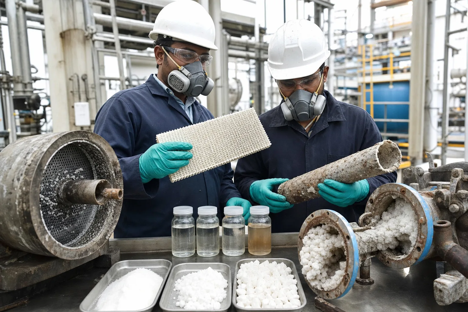 11Tube bundle or demister deposits22Clean separator/nucleation internal33Scaled pipe and crystal blockage44Mother liquor and solid samples
What to identify
- 1Tube bundle or demister deposits
- 2Clean separator/nucleation internal
- 3Scaled pipe and crystal blockage
- 4Mother liquor and solid samples
What the image proves
Hard scale, crystal plugging, droplet carryover and organic liquor contamination can coexist and require different corrections.
How to verify it
After cooling, draining, LOTO and exposure control, preserve location-specific samples and correlate chemistry, phase and corrosion with the operating history.
Nine steps from wastewater to reusable water and solids
Volume, salinity, phase and energy duty change at every step.
1. Segregate and equalize
Source streams → compatible feeds
Stabilize load and isolate reactive, volatile, fouling or corrosive streams.
2. Pretreat
Hardness/silica/solids/oil/organics → residuals
Protect membranes and thermal equipment and define the solids route.
3. Recover water by membrane
Feed → permeate + concentrate
Recover the lower-energy water fraction within pressure and saturation limits.
4. Condition concentrate
Brine → pH/degassing/softening/antifoam/seed prep
Control corrosion, volatile carryover, foam and crystal phase.
5. Evaporate
Brine + heat/compression → vapor + near-saturated liquor
Remove more water while recycling latent heat where possible.
6. Condense vapor
Vapor → distillate
Recover reuse water and detect entrainment or volatile carryover.
7. Crystallize
Saturated liquor → crystals + mother liquor
Use seeds and circulation for controlled growth instead of surface scale.
8. Dewater solids
Slurry → wet salt + centrate
Control seed inventory, liquor recycle and cake moisture.
9. Manage endpoints
Reuse water + solids + residuals → declared outlets
Release water, qualify or dispose solids, and account for cleaning and vent residues.
Distinct duties across the ZLD train
Separate each unit's job, limit and evidence before diagnosing the chain.
Pretreatment and membranes
- Duty
- Remove limiting species, recover water and minimize thermal feed volume.
- Typical failure
- Fouling, scale, excess osmotic pressure or incompatible mixing.
- Evidence
- Normalized flux/rejection, DP, saturation, concentrate flow and ion/organic balance.
Evaporation and separation
- Duty
- Boil high-salt feed, reuse vapor energy and produce distillate.
- Typical failure
- Scale, corrosion, foam, entrainment or compressor off-design.
- Evidence
- Heat-transfer coefficient, vacuum, vapor economy, kW and distillate chemistry.
Crystallizer and slurry loop
- Duty
- Control supersaturation, seed inventory, growth and slurry withdrawal.
- Typical failure
- Excess nucleation, weak circulation, fines or wrong salt phase.
- Evidence
- Slurry density, PSD, circulation, phase, salt yield and deposits.
Dewatering and endpoints
- Duty
- Remove liquor and produce characterized solids and released water.
- Typical failure
- Wet impure cake, liquor accumulation, no solids outlet or hidden CIP liquid.
- Evidence
- Dry mass, moisture/purity, inventory, water release and disposal records.
A ZLD claim needs a stated facility boundary and time period. Rainwater, sanitary wastewater, drains, CIP, laboratory liquid, wet-solid leachate and off-site liquids must be included or explicitly excluded.
Four synchronized evidence sets
Water and inventory
Feed, permeate, concentrate, distillate, slurry, cake moisture, tank levels and cleaning water.
Salt and phase
Key ions, saturation, mother-liquor density, dry salt, mineral phase, PSD, deposits and entrained liquor.
Heat and electricity
Steam, MVR/MVC power, temperature difference, vacuum, circulation and membrane pumping.
Quality and availability
Permeate/distillate release, uptime, cleaning frequency, solids outlet and compliance.
Diagnose with water–salt–heat–solids evidence
- Signal
- Thermal feed and energy rise while permeate falls
- Likely cause
- Membrane fouling/scale, recovery loss or pretreatment failure
- First action
- Normalize membrane data and close concentrate/saturation before cleaning
- Signal
- Temperature/power rises while evaporation falls
- Likely cause
- Heat-transfer scale, low circulation, vacuum or compressor fault
- First action
- Check U-value, circulation, deposits and compressor point
- Signal
- Fines/plugging rise but salt yield does not close
- Likely cause
- Supersaturation, seed inventory, withdrawal or phase failure
- First action
- Measure slurry density, PSD and phase; correct circulation and withdrawal
- Signal
- Distillate conductivity/TOC/ammonia rises
- Likely cause
- Entrainment, foam, demister failure or volatile carryover
- First action
- Separate ionic/volatile tests and inspect level, foam and demisting
Four misconceptions
ZLD means boiling away every drop
Membranes usually recover lower-energy water first; the objective is no liquid-waste discharge, not wasting all water.
White salt is saleable
Phase, metals, organics and mother liquor determine whether solids are products or wastes.
Maximum recovery is always best
Osmotic, saturation, viscosity, corrosion and energy limits create a system optimum.
No drain proves ZLD
Inventory, wet solids, off-site liquid, CIP, vent condensate and leaks still require long-term accounting.